TM-9-2330-356-14
SEMITRAILER, TANK: 5000 GALLON, BULK HAUL, SELF LOAD/UNLOAD M967 AND M967A1; SEMITRAILER, TANK: 5000 GALLON, FUEL DISPENSING, AUTOMOTIVE M969 AND M969A1; SEMITRAILER, TANK: 5000 GALLON, FUEL DISPENSING, UNDER/OVERWING AIRCRAFT M970 AND M970A1
TECHNICAL MANUAL; OPERATOR’S, UNIT, DIRECT SUPPORT, AND GENERAL SUPPORT MAINTENANCE MANUAL
OCTOBER 1990
TM-9-2330-356-14 - Page 322 of 528
TM 9-2330-356-14
Section IV. REMOVAL AND INSTALLATION OF MAJOR COMPONENTS
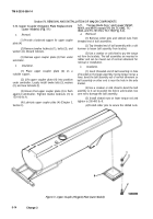
5-10. Upper Coupler (Kingpin) Plate Replacement
(Later Models) (Fig. 5-1)
a.
Removal.
(1) Provide a balanced support for upper coupler
plate
(4).
(2)
Remove twelve locknuts (1), bolts (3), and
washers (2). Discard locknuts.
(3) Remove upper coupler plate (4) from under
semitrailer.
b.
Installation.
(1) Place upper coupler plate (4) on a
suitable support.
(2) Lift upper coupler plate (4) into position
under semitrailer. Loosely install twelve bolts (3), washers
(2), and new locknuts (l).
(3) Ensure that upper coupler plate (4) is flush
against semitrailer. Tighten twelve locknuts (1) to
130-140 lb.-ft.
(4) Lubricate upper coupler plate (4) (Chapter 3,
Section I).
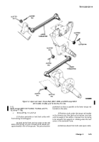
5-11.
Torque Rods (Up r and Lower) M967,
M969, and M970 except 970 SN TC-0843, TC-
0844, and TC-103 thru TC-178) (Fig. 5-2).
a.
Removal.
(1) Remove cotter pins and slotted nuts from
threaded end of ball assemblies.
(2) Tap threaded end of ball assembly with a soft
hammer to loosen ball assembly from bracket.
(3) Use a crowbar or cold chisel to pry the torque
rod from the brackets. The ball assemblies are mounted in
robber and can be moved out of normal alinement for
removal or installation.
b.
Installation.
(1) insert threaded end of ball assembly in hole
of bracket on the bogie assembly. Using torque rod as a
lever, bend the ball assembly out of normal alinement so
ball assembly on other end is near the hole in the axle
bracket.
(2) Use a crowbar or cold chisel to bend the ball
assembly so it can be pushed into hole in axle bracket. Use
care not to damage the ball assembly.
(3) Install slotted nuts on lower torque rod and
tighten to 350-400 lb.-ft.
(4)
Install cotter pins to secure the slotted nuts.
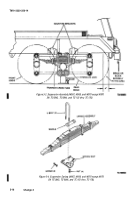
Figure 5-1, Upper Coupler (Kingpin) PIate (Later Models)
5-14
Change 3
Back to Top

