TM-9-2330-356-14
SEMITRAILER, TANK: 5000 GALLON, BULK HAUL, SELF LOAD/UNLOAD M967 AND M967A1; SEMITRAILER, TANK: 5000 GALLON, FUEL DISPENSING, AUTOMOTIVE M969 AND M969A1; SEMITRAILER, TANK: 5000 GALLON, FUEL DISPENSING, UNDER/OVERWING AIRCRAFT M970 AND M970A1
TECHNICAL MANUAL; OPERATOR’S, UNIT, DIRECT SUPPORT, AND GENERAL SUPPORT MAINTENANCE MANUAL
OCTOBER 1990
TM-9-2330-356-14 - Page 329 of 528
TM 9-2330-356-14
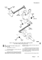
5-17.
Bogie Assembly M967A1, M969A1, and
M970A1 including M970 SN TC-0843, TC-0844, and
TC-103 thru TC-178).
a.
Removal.
(1) Position semitrailer on hard, level surface
with front resting on landing gear.
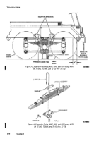
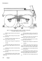
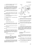
(2) Jack up rear of semitrailer and support under
frame securely until weight of semitrailer is removed from
springs and axles (fig. 5-5).
(3) Release air from both air reservoirs by
opening drain cocks on bottom of reservoirs (fig. 4-79).
(4) Tag and disconnect eight hoses from brake air
chambers on both axles. Manually release the fail-safe
springs para 2-4).
(5) Position a jack under the trunnion tube close
to the inside of each trunnion hanger to support weight of
trunnion tube.
(6) Remove four nuts, four washers, and four
bolts which fasten the trunnion hanger to the mounting
bracket. Repeat for opposite side.
(7) Remove jacks from under trunnion tube.
Raise semitrailer until there is enough clearance to roll
the bogie assembly and wheels out from under rear of
semitrailer (fig. 5-5).
(8) Lower semitrailer onto supports or cribbing
after bogie assembly is removed (fig 5-5).
b.
Installation.
(1) Raise rear of semitrailer to allow bogie
assembly to roll under frame from rear. With front of
bogie assembly toward front of semitrailer, roll bogie
assembly into position under mounting brackets for the
trunnion hangers.
(2) Position a jack under trunnion tube as close as
possible to the inside of each trunnion hanger.
(3) Lower the semitrailer to within l-inch of the
trunnion hangers.
(4) Aline holes in mounting bracket with holes in
trunnion hanger.
(5) Install four capscrews, four washers, and four
nuts. As the nuts are tightened, jack up trunnion tube to
seat the trunnion hanger. Tighten nuts to 90 lb.-ft.
(6) Tighten two trunnion capscrews and nuts.
(7) Repeat steps (4) through (6) for opposite side.
(8) Connect eight hoses to brake air chambers on
both axles as tagged. Manually release the fail-safe springs
(pars 2-4).
(9) Remove jacks and supports, and lower
semitrailer to ground.
5-18. Engine and Pump Assembly
NOTE
The engino and pump assembly is re-
moved and installed as a unit power plant.
Removal of the complete module is neces-
sary to remove the engine.
The pump can be removed without remov-
ing the complete module.
a.
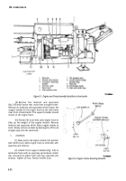
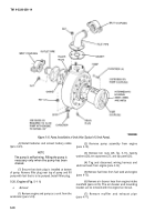
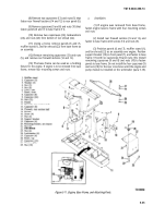
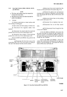
Removal (Fig 5-7).
(1) Disconnect negative, then positive battery
cables from batteries (l).
(2) Remove self-tapping screws from muffler
shroud (2). Remove muffler shroud.
(3) Remove the alternator adjusting bracket (3) .
from the alternator to get clearance for removal of
throttle cable.
(4) Loosen wing screws and remove panel door
(5) on air housing. Remove throttle cable (4) (para 4-75).
(5) Remove ¼-inch oil pressure tube (7) for oil
pressure gage from oil adapter. Remove ¼-inch fuel
pressure tube (6) from primary filter. Cut the tie straps,
then pull oil pressure tube and fuel pressure tube from the
engine compartment.
(6) Disconnect control panel wiring harness plug
(8) from junction box on engine frame by turning
counterclockwise with hook-type spanner wrench.
CAUTION
Ensure that fuse has been removed first to
prevent damage.
(7) Disconnect electrical lead for hose reels
(M969, M969A1, M970, and M970A1) above and to right
of fuse (para 4-27). Follow control panel wiring harness
disconnected above, and remove two nuts and capscrews
securing conduit mounting plate to middle of engine
frame behind engine.
(8) Remove split couplings, and disconnect pump
inlet and outlet lines from the centrifugal pump (10).
Change 3
5-21
Back to Top

