TM-9-2330-356-14
SEMITRAILER, TANK: 5000 GALLON, BULK HAUL, SELF LOAD/UNLOAD M967 AND M967A1; SEMITRAILER, TANK: 5000 GALLON, FUEL DISPENSING, AUTOMOTIVE M969 AND M969A1; SEMITRAILER, TANK: 5000 GALLON, FUEL DISPENSING, UNDER/OVERWING AIRCRAFT M970 AND M970A1
TECHNICAL MANUAL; OPERATOR’S, UNIT, DIRECT SUPPORT, AND GENERAL SUPPORT MAINTENANCE MANUAL
OCTOBER 1990
TM-9-2330-356-14 - Page 336 of 528
TM 9-2330-356-14
WARNING
Ensure that forklift is properly positioned
under cabinet. The entire weight of the
cabinet is now on the forklift. Failure to follow
this warning may result In cabinet falling and
injuring personnel.
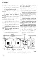
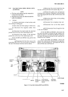
(9) Position a forklift and lift the cabinet slightly
to relieve pressure on the mounting screws and nuts.
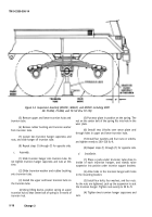
(10) Remove eighteen mounting screws and
self-locking nuts (7, top left side; 8, top right side; and 3,
bottom left side).
CAUTION
Before removing the cabinet, ensure that all
disconnections have been made.
(11) Lower the cabinet slightly and pull the lead
from the junction box at the rear of the cabinet.
(12) Remove cabinet.
b.
Installation.
WARNING
Ensure that forklift is properly positioned
under cabinet. The entire weight of the
cabinet is now on the forklift. Failure to follow
this warning may result In cabinet falling and
Injuring personnel.
(4) Thread lead to the inside of the junction box
on rear of cabinet.
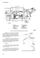
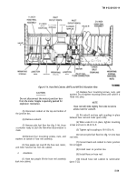
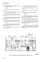
(5) On the M970 and M970A1, do the following
(fig. 5-13):
(a)
Thread disconnected lines through the
hole at the rear of cabinet.
(b)
Connect line to the flow control valve.
(c)
Connect line to the deadman hose reel.
(d)
Connect three lines to the parking brake
control valve (para 4-47).
(e)
Install cabinet door and frame assembly.
Attach frame to hose trough and cabinet hose with ten
capscrews, flatwashers, and self-locking nuts.
(f)
Connect the control cable to the trip bar
on the top, left side of the cabinet.
(g)
Connect the line that runs to the
accumulator (fig. 4-151).
(6) Connect the conduit to the junction box,
(7) Connect the lead to the inside of the junction
box on the rear of the cabinet (para 4-27).
(8) Connect negative battery cables to batteries.
(9) Operate dispensing equipment and check for
leaks (table 2-1).
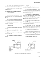
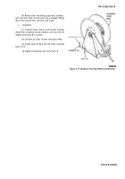
5-23. Hose Reel Assembly-2½-inch (Fig. 5-14)
a.
Removal.
NOTE
NOTE
Ensure that all lines are connected as tagged.
The 2½-inch hose reel, hose reel motor, and
electrical junction box will be removed as a
(1) Position a forklift under the hose reel cabinet.
unit in this procedure.
(2) Position hose reel cabinet under semitrailer
and fasten with eighteen capscrews and self-locking nuts
(7, top left side; 8, top right side; and 3, bottom left side).
Remove forklift.
(3) On M969 and M969A1, install split couplings
to connect both inlet piping to meter inlet tubes
(para 4-85). On M970 and M970A1, install split coupling
behind hose reel cabinet to connect inlet piping to meter
inlet tube.
Tighten split coupling capscrews to
95-105 lb.-ft.
(1) Remove hose reel cabinet from semitrailer
(para 5-22).
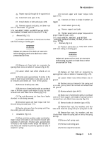
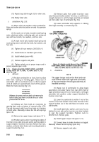
(2) Remove 2½-inch hose from reel by releasing
quick disconnect coupling.
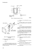
(3) Remove cover from motor junction box
(fig. 5-14).
(4) Tag and disconnect leads that enter from the
top and bottom of the box.
5-28
Back to Top

