TM-9-2330-356-14
SEMITRAILER, TANK: 5000 GALLON, BULK HAUL, SELF LOAD/UNLOAD M967 AND M967A1; SEMITRAILER, TANK: 5000 GALLON, FUEL DISPENSING, AUTOMOTIVE M969 AND M969A1; SEMITRAILER, TANK: 5000 GALLON, FUEL DISPENSING, UNDER/OVERWING AIRCRAFT M970 AND M970A1
TECHNICAL MANUAL; OPERATOR’S, UNIT, DIRECT SUPPORT, AND GENERAL SUPPORT MAINTENANCE MANUAL
OCTOBER 1990
TM-9-2330-356-14 - Page 340 of 528
TM 9-2330-356-14
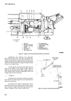
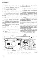
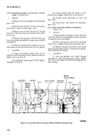
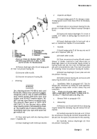
Figure 5-17, Fabrication Instructions for Ferrule.
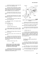
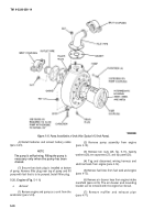
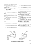
Figure 5-18. Probe Assembly Installed in Meter
Outlet Nipple.
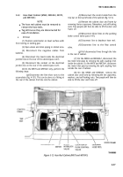
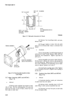
5-27. Meter Assembly (M970 and M970A1)
(Fig. 5-1 4)
a.
Removal.
(1) Remove split couplings from nipples on both
sides of meter. Slide the coupling gaskets onto pipe ends
away from the meter. At rear of meter, remove four nuts
from studs on meter inlet.
5-32
(2) Remove
Remove meter.
(3) Flanged
four mounting screws and nuts,
nipples on meter inlet and outlet
ports can be removed after meter is removed from
cabinet.
b.
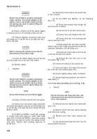
Installation.
(1) Use new gaskets. Install flanged nipples on
outlet ports of meter. Fasten flange to meter with four
capscrews and lockwashers. Tighten capscrews to
50-75 lb.-ft.
(2) Put new gasket over studs on meter inlet port.
Position meter in cabinet and connect to inlet piping with
four self-locking nuts. Tighten nuts to 50-75 lb.-ft. Install
four screws, flatwashers, and self-locking nuts to fasten
meter to cabinet. Tighten to 67-74 Ib.-ft.
(3) Install split couplings (para 4-85). Tighten
2-inch coupling to 57-63 Ib.-ft. Tighten 3-inch coupling to
95-105 lb.-ft.
5-28.
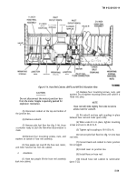
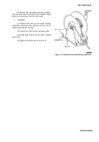
Deadman Hose Reel (M970 and M970A1)
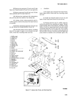
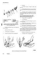
(Fig. 5-19)
a.
Removal.
(1) Deactivate deadman system per instructions
on plate inside hose reel cabinet.
(2) Remove meter assembly (para 5-27) and
valve R (fig. 5-14) for access to deadman hose reel.
(3) Disconnect air lines from ports on both sides
of hose reel (para 4-89).
Back to Top

