TM-9-2330-356-14
SEMITRAILER, TANK: 5000 GALLON, BULK HAUL, SELF LOAD/UNLOAD M967 AND M967A1; SEMITRAILER, TANK: 5000 GALLON, FUEL DISPENSING, AUTOMOTIVE M969 AND M969A1; SEMITRAILER, TANK: 5000 GALLON, FUEL DISPENSING, UNDER/OVERWING AIRCRAFT M970 AND M970A1
TECHNICAL MANUAL; OPERATOR’S, UNIT, DIRECT SUPPORT, AND GENERAL SUPPORT MAINTENANCE MANUAL
OCTOBER 1990
TM-9-2330-356-14 - Page 333 of 528
TM 9-2330-356-14
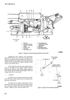
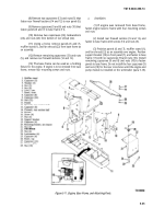
(8) Remove two capscrews (13) and nuts (5) that
fasten rear firewall sections (14 and 12) to rear panel (6).
(9) Remove capscrews (9 and 8) and nuts (10) that
fasten panels (6 and 7) to base frame (11).
(10) Remove two capscrews (25), lockwashers
(24), and nuts (23) from bottom of fan shroud (22).
(11) Using a hoist, remove panels (6 and 7),
muffler stand (1), and fan shroud (22) from base frame as
an assembly.
(12) Remove remaining capscrews (13) and nuts
(5), and remove rear firewall sections (14 and 12).
(13) The base frame can be used as a holding
fixture for the engine. If engine is to be removed from base
frame, remove four mounting screws and nuts.
b.
Installation.
(1) If engine was removed from base frame,
fasten engine base to frame with four mounting screws
and nuts.
(2) Install rear firewall sections (14 and 12), and
fasten to base frame with screws (13) and nuts (5).
(3) Position panels (6 and 7), muffler stand (1),
and fan shroud (22) as an assembly over engine. Position
support bracket (18) on front panel (7), and fasten to base
frame (11) with six capscrews (9) and nuts (10). Install
remaining capscrews (9 and 8) and nuts (10) to fasten
panels to base frame. Do not install the four capscrews (9)
and nuts (10) for the rear cross brace until the engine and
pump module is installed on the semitrailer (para 5-18).
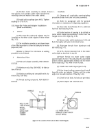
Figure 5-11. Engine, Base Frame, and Attaching Parts.
5-25
Back to Top

