TM-9-2330-356-14
SEMITRAILER, TANK: 5000 GALLON, BULK HAUL, SELF LOAD/UNLOAD M967 AND M967A1; SEMITRAILER, TANK: 5000 GALLON, FUEL DISPENSING, AUTOMOTIVE M969 AND M969A1; SEMITRAILER, TANK: 5000 GALLON, FUEL DISPENSING, UNDER/OVERWING AIRCRAFT M970 AND M970A1
TECHNICAL MANUAL; OPERATOR’S, UNIT, DIRECT SUPPORT, AND GENERAL SUPPORT MAINTENANCE MANUAL
OCTOBER 1990
TM-9-2330-356-14 - Page 326 of 528
TM 9-2330-356-14
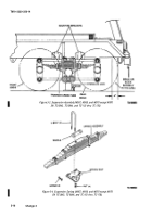
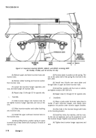
Figure 5-5. Suspension Assembly (M967A1, M969A1, and M970A1 including M970
SN TC-0843, TC-0844, and TC-103 thru TC-178).
(5) Remove upper and lower trunnion hubs and
trunnion tube.
(6) Remove rubber bushing and trunnion washer
from trunnion tube.
(7) Loosen two trunnion hanger capscrews and
nuts, and slide hanger off trunnion tube.
(8) Repeat steps (1) through (7) for opposite side.
c.
Assembly.
(1) Slide trunnion hanger onto trunnion tube. Do
not tighten trunnion hanger capscrews and nuts at this
time.
(2) Slide trunnion washer and rubber bushing
onto trunnion tube.
(3) Install the upper and lower trunnion hubs on
the trunnion tube.
(4)
Using lifting device, position spring on upper
trunnion hub so that center bolt of spring is in recess of
trunnion hub.
(5) Put wear plate in position on the spring. The
nut on the center bolt of the spring fits into hole in the
wear plate.
(6) Install two U-bolts over wear plate and
through holes in upper and lower trunnion hubs.
(7) Install four washers and four nuts on U-bolts,
and tighten evenly to 200--320 lb.-ft.
(8) Repeat steps (1) through (7) for opposite side.
d.
Installation.
(1) Place a jack under trunnion tube close to
inside of each trunnion hanger, and slowly raise
suspension into position under trunnion support brackets.
(2) Aline holes in the trunnion hanger with holes
in the mounting bracket.
(3) Install four bolts, four washers, and four nuts.
As the nuts are tightened, jack up the suspension to seat
the trunnion hanger. Tighten nuts evenly to 90 lb.-ft.
(4) Tighten two trunnion hanger capscrews and
nuts.
5-18
Change 3
Back to Top

