TM-9-2330-356-14
SEMITRAILER, TANK: 5000 GALLON, BULK HAUL, SELF LOAD/UNLOAD M967 AND M967A1; SEMITRAILER, TANK: 5000 GALLON, FUEL DISPENSING, AUTOMOTIVE M969 AND M969A1; SEMITRAILER, TANK: 5000 GALLON, FUEL DISPENSING, UNDER/OVERWING AIRCRAFT M970 AND M970A1
TECHNICAL MANUAL; OPERATOR’S, UNIT, DIRECT SUPPORT, AND GENERAL SUPPORT MAINTENANCE MANUAL
OCTOBER 1990
TM-9-2330-356-14 - Page 331 of 528
TM 9-2330-356-14
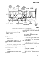
(3) Install split couplings to connect pump inlet
and outlet lines to tank piping (para 4-85).
(4) Attach conduit mounting plate to middle of
engine frame with two screws and locknuts (para 4-25).
Connect wiring harness plug (8, fig. 5-7) to junction box.
Connect electrical lead for hose reels (M969, M969A1,
M970, and M970A1) to buss bar, and install cover.
(5) Install ¼-inch oil pressure tube (7, fig. 5-7) to
oil adapter. Install ¼-inch fuel pressure tube (6) to primary
falter.
(6) Install throttle cable (para 4-75). Install
panel door (5) on air housing. Install alternator adjusting
bracket (3) to alternator.
(7) Install muffler shroud (2) over muffler and
secure with self-tapping screws.
(8) Connect positive,
then negative battery
cables to batteries.
5-19. Centrifugal Pump
a.
Removal (Fig. 5-10).
(1) Remove batteries (para 4-23).
(2) Drain piping. Drain filter/separator (M969,
M969A1, M970, M970A1). Make sure tank is empty of
fuel.
(3) Remove drain plug on bottom of pump and
drain fuel from pump.
(4) Remove pump inlet and outlet lines
(para 4-91).
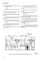
(5) Remove screws which fasten two halves of
rear firewall (fig. 5-9) to engine frame. Move the
half-sections aside to allow for removal of the pump. Do
not remove the fuel pumps or buss bar assembly from
firewall sections.
(6) Remove alternator (para 4-78).
NOTE
It will be necessary to turn engine crankshaft
clockwise with a socket wrench Inserted
through grille on flywheel housing to reach
both capscrews on pump coupling.
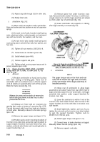
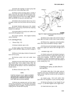
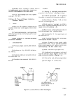
(7) Remove two capscrews and nuts from engine
half of pump coupling (fig. 5-10). The engine half of pump
coupling will remain on engine. The pump half of the
coupling will be removed with the pump.
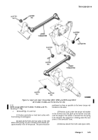
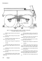
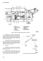
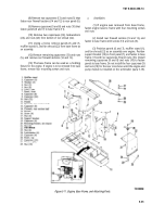
Figure
5-9.
Engine and Pump Assembly Removed From
Semitrailer
(8) Remove two screws and nuts from base of
pump. Mark the location of shims used in pump mounting.
(9) Remove four capscrews and lockwashers
which fasten pump intermediate housing to engine.
(10) Pull pump and intermediate housing straight
away from engine and remove them through rear of
frame.
b.
Installation (Fig. 5-10).
(1) Position pump and intermediate housing on
engine, alining pump half of coupling with engine half of
pump drive coupling.
Install four capscrews and
lockwashers to fasten intermediate housing to engine.
Install two capscrews and nuts to secure two halves of
pump coupling (fig. 5-10).
If Installing same
same positions.
NOTE
pump, use same shims In
(2) Position shims (fig. 5-10) under pump as
required to aline pump mounting with engine mounting to
within .03-inch. Install two screws and nuts, and tighten to
142-158 lb.-ft.
(3) Install pump
inlet and outlet lines
(para 4-90). Use new gaskets on pump mounting flanges.
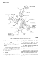
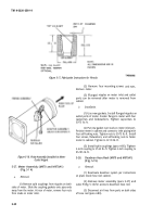
(4) Position half-sections of rear firewall (12 and
14, fig. 5-1 1), and fasten together and to engine frame.
(5) Install alternator (para 4-78).
5-23
Back to Top

