TM-9-2330-356-14
SEMITRAILER, TANK: 5000 GALLON, BULK HAUL, SELF LOAD/UNLOAD M967 AND M967A1; SEMITRAILER, TANK: 5000 GALLON, FUEL DISPENSING, AUTOMOTIVE M969 AND M969A1; SEMITRAILER, TANK: 5000 GALLON, FUEL DISPENSING, UNDER/OVERWING AIRCRAFT M970 AND M970A1
TECHNICAL MANUAL; OPERATOR’S, UNIT, DIRECT SUPPORT, AND GENERAL SUPPORT MAINTENANCE MANUAL
OCTOBER 1990
TM-9-2330-356-14 - Page 337 of 528
TM 9-2330-356-14
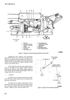
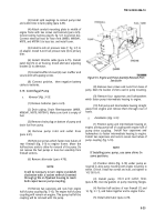
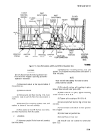
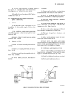
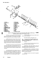
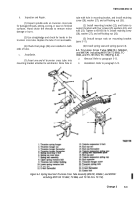
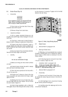
Figure 5-14. Hose Reel Cabinet, (M970 and M970A1) Roadside View.
CAUTION
Do not disconnect the motor junction box
from the motor. Nipple is specially packed for
explosion resistance.
(5) Disconnect conduit at the top and bottom of
the junction box.
(6) Remove valve R.
(7) Remove pilot fuel flow line (fig. 5-14). Have
a container ready to catch the flow when disconnection is
made.
(8) Remove four mounting screws, nuts, and
washers on bottom of hose reel assembly.
(9) Two people can now lift the hose reel, motor,
and motor function box from the cabinet.
b.
Installation.
(1) Have two people lift the hose reel assembly
back into cabinet.
(2) Replace four mounting screws, nuts, and
washers. Do not tighten mounting screws until valve R is
fitted into place.
NOTE
Hose reel will slide slightly from side to side to
allow room for valve R.
(3) Fit valve R and two split couplings in place
between hose reel and meter (para 4-85).
(4) When valve R is in place, tighten mounting
screws and nuts to 20-35 lb.-ft.
(5) Tighten split coupling to 95-105 lb.-ft.
(6) Connect pilot fuel flow line (fig. 5-14) to hose
reel inlet.
(7) Connect leads and conduit to motor junction
box as tagged.
.
(8) Install cover on junction box.
(9) Install hose on hose reel.
(10) Install hose reel cabinet to semitrailer
(para 5-22).
5-29
Back to Top

