TM-9-2330-356-14
SEMITRAILER, TANK: 5000 GALLON, BULK HAUL, SELF LOAD/UNLOAD M967 AND M967A1; SEMITRAILER, TANK: 5000 GALLON, FUEL DISPENSING, AUTOMOTIVE M969 AND M969A1; SEMITRAILER, TANK: 5000 GALLON, FUEL DISPENSING, UNDER/OVERWING AIRCRAFT M970 AND M970A1
TECHNICAL MANUAL; OPERATOR’S, UNIT, DIRECT SUPPORT, AND GENERAL SUPPORT MAINTENANCE MANUAL
OCTOBER 1990
TM-9-2330-356-14 - Page 346 of 528
TM 9-2330-356-14
Section III. BRAKES AND BRAKE SYSTEM COMPONENTS
6-6.
Brake Shoes (Fig. 6-3)
a.
Disassembly.
WARNING
Due to asbestos hazard, do not grind off rivet
heads. Failure to follow this warning may re-
sult in injury or death to personnel.
(1) Punch rivets out from back side of shoe using
a hammer and a drift or punch.
(2) Remove linings from brake shoes.
b.
Inspection
and
Repair.
(1) Oil or grease saturated linings are not
reusable. Saturated linings indicate leakage in the axle
shaft seals.
(2) Grooving or uneven wear in brake linings in-
dicates a need for refacing or replacement of brake drum.
(3) Inspect brake shoe for distortion, cracks or
damage. Replace the brake shoe if these conditions are
found. Lining and shoe contact surfaces should be clean
and smooth.
(4) Use new rivets of the correct body diameter,
head size and shape, length, and material.
c.
Assembly.
NOTE
Do not use combination linings.
(1) Make sure lining and shoe contact surfaces
are clean.
(2) Clamp lining to brake shoe with C-clamps
with rivet holes in both pieces alined.
(3) Drive the rivets squarely into the holes with a
7/16-inch flat head drift.
(4) Position the C-clamps as close to the rivet
holes as possible and make certain the lining is tight
against the shoe.
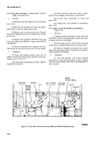
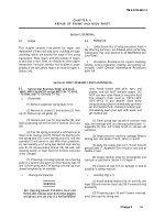
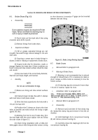
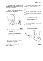
(5) Working from heel to toe of brake shoe, form
the rivet heads with the correct tubular rivet set. Follow
the order shown in figure 6-3.
(6) Check lining installation with a 0.002-inch
feeler gage to ensure that lining and shoe contact. Lining
to shoe clearance is excessive
between shoe and lining.
if gage can be inserted
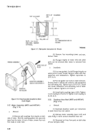
Figure 6-3.
Brake Lining Riveting Sequence.
6-7.
Brake Drums
a.
Removal.
Refer to paragraph 4-49.
b.
Reboring of Brake Drums.
(1) Reboring is not recommended due to reduced
strength of refaced drums. If it is necessary to rebore a
drum, remove as little metal as necessary to true the
friction surface.
(2) If reboring requires removal of more than
1/16-inch of material, replace the drum.
c.
Installation.
Refer to paragraph 4-49.
6-8.
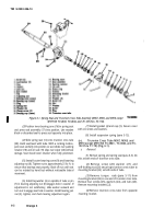
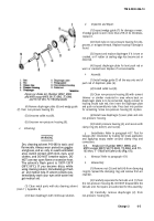
Brake Air Chamber M867, M969, and
M970 except M970 SN TC-0843, TC-0844, and TC-
103 thru T -178) (Standard) (Fig. 6-4).
a.
Removal.
Refer to paragraph 4-37.
b.
Disassembly.
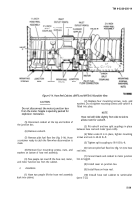
(1) Remove nut (2) and bolt (1) from clamp ring
(3). Spread the clamp ring and remove it from the air
chamber.
(2) Hold diaphragm (5) to non-pressure housing
(8) and remove pressure housing (4).
(3) Carefully remove the diaphragm (5) from the
non-pressure housing (8).
6-4
Change 3
Back to Top

