TM-9-2330-356-14
SEMITRAILER, TANK: 5000 GALLON, BULK HAUL, SELF LOAD/UNLOAD M967 AND M967A1; SEMITRAILER, TANK: 5000 GALLON, FUEL DISPENSING, AUTOMOTIVE M969 AND M969A1; SEMITRAILER, TANK: 5000 GALLON, FUEL DISPENSING, UNDER/OVERWING AIRCRAFT M970 AND M970A1
TECHNICAL MANUAL; OPERATOR’S, UNIT, DIRECT SUPPORT, AND GENERAL SUPPORT MAINTENANCE MANUAL
OCTOBER 1990
TM-9-2330-356-14 - Page 348 of 528
TM 9-2330-356-14
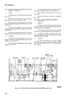
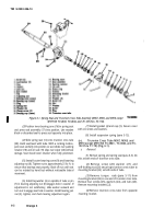
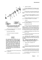
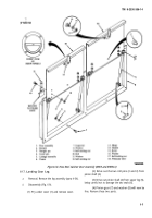
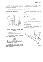
Figure 6-5. Brake Air Chamber (M967, M969, and
M97O except M970 SN TC-0843, TC-0844, and TC-103
thru TC-178) (Fail-Safe Unit).
(4) Remove diaphragm plate (3) and wedge guide
(7) from housing.
(5) Remove collet nut (9).
c.
Cleaning.
Refer to paragraph 6-8.
d.
Inspection and Repair.
Refer to paragraph 6-8.
e.
Assembly.
(1) Perform steps 1 through 4 under para-
graph 6-8.
(2) Assemble fail-safe unit (1) to non-pressure
housing, and secure with clamp ring (6), bolt (4), and nut
(5).
f.
Installation. Refer to paragraph 4-39. Test for
leakage after installation by making full brake application
and applying soapy water around clamp ring and
connections.
6-10. Non-adjusting Brake Plunger M967
M969, and M970 except M970 SN TC-843, TC-
0844, and TC-103 thruTC-178) (Fig. 6-6).
a.
RemovaI.
Refer to paragraph 4-36.
b.
Seal Replacement.
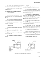
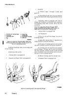
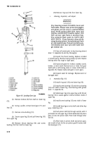
(1) Pry or cut old seal from plunger. Use care not
to damage plunger.
(2) Apply film of grease (item 17, Appendix E) to
inside surfaces of new seal assembly.
(3) Put apiece of masking tape over slot for brake
shoe web in plunger to protect seal during installation.
(4) Carefully push the double-lip seal assembly
onto the plunger. The outer seal lip must be stretched
over nose of plunger. Continue to push on seal until inner
seal is completely in the second plunger groove and outer
seal lip is in the first plunger groove.
(5) Remove masking tape from plunger nose.
c.
Installation.
Refer to paragraph 4-36.
Figure 6-6. Installing Seal on Non-Adjusting Plunger
6-6
Change 3
Back to Top

