TM-9-2330-356-14
SEMITRAILER, TANK: 5000 GALLON, BULK HAUL, SELF LOAD/UNLOAD M967 AND M967A1; SEMITRAILER, TANK: 5000 GALLON, FUEL DISPENSING, AUTOMOTIVE M969 AND M969A1; SEMITRAILER, TANK: 5000 GALLON, FUEL DISPENSING, UNDER/OVERWING AIRCRAFT M970 AND M970A1
TECHNICAL MANUAL; OPERATOR’S, UNIT, DIRECT SUPPORT, AND GENERAL SUPPORT MAINTENANCE MANUAL
OCTOBER 1990
TM-9-2330-356-14 - Page 357 of 528
TM 9-2330-356-14
CHAPTER 7
REPAIR OF ENGINE ASSEMBLY
Section 1. DESCRIPTION
7-1.
Scope
a.
This chapter contains instructions for direct and
general support maintenance of the engine and related
parts which are beyond the scope of using organization.
b.
The terms right, left, front, and rear used in this
technical manual, with reference to the engine and its
components, are determined as viewed from the front or
flywheel end of engine.
7-2.
General
The diesel engine assembly, Model DJCMS
4118W (fig. 5-9) is a 4-cylinder, 4-cycle, valve-in-head,
aircooled engine.
b.
The engine is used as a power source to drive a
pump assembly for fueling and defueling operations.
c .
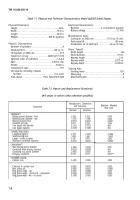
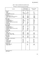
Physical
and technical characteristics are
tabulated in table 7-1.
AND SPECIFICATIONS
d.
The following systems and components comprise
the Model DJCMS 4118W Diesel Engine:
(1)
(2)
(3)
(4)
(5)
(6)
(7)
Air cooling system (para 7-3)
Fuel system (para 7-4)
Lubrication system (para 7-5)
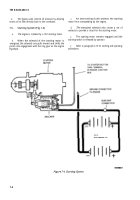
Starting system (para 7-6)
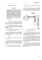
Charging system (para 7-7)
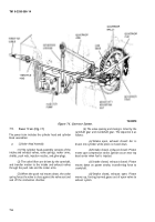
Governor system (para 7-8)
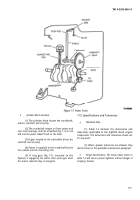
Power train (para 7-9)
7-3.
Air Cooling System (Fig. 7-1)
a.
The engine has a pressure air cooling system. Fins
on the engine blower (flywheel) draw air into the front of
the engine housing and force it past the cylinders and out
the right side of the engine.
Figure 7-1. Air Cooling System.
7- 1
Back to Top

