TM-9-2330-356-14
SEMITRAILER, TANK: 5000 GALLON, BULK HAUL, SELF LOAD/UNLOAD M967 AND M967A1; SEMITRAILER, TANK: 5000 GALLON, FUEL DISPENSING, AUTOMOTIVE M969 AND M969A1; SEMITRAILER, TANK: 5000 GALLON, FUEL DISPENSING, UNDER/OVERWING AIRCRAFT M970 AND M970A1
TECHNICAL MANUAL; OPERATOR’S, UNIT, DIRECT SUPPORT, AND GENERAL SUPPORT MAINTENANCE MANUAL
OCTOBER 1990
TM-9-2330-356-14 - Page 361 of 528
TM 9-2330-356-14
7-7.
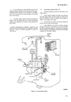
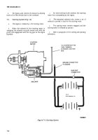
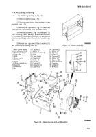
Charging System (Fig. 7-5)
CAUTION
Instantaneous damage will be caused to the
voltage regulator if system polarity is
reversed. Installing a battery backwards,
boosting or jump starting with jumper
connected backwards, or reversing the
positive (+) and negative (-) output leads of
the alternator will damage the regulator.
Although the polarity reversal may only be
momentary, and may not damage the
alternator diodes, the voltage regulator will
still be damaged.
a.
Description.
(1) The charging system supplies approximately
14V of direct current for recharging the batteries and
operating the components of the engine electrical system.
(2) The system includes two 12V batteries
connected in parallel, an alternator with integral voltage
regulator, a voltmeter, and wiring to connect these
components together.
(3) The self-load-limiting alternator has a
built-in solid state voltage regulator.
(4) The voltage regulator is a “J’’-type regulator
equipped with transient voltage protection to withstand
instantaneous opening of the charging circuit under
full-load conditions.
b.
Operation.
(1) The alternator is belt driven off the pump
drive coupling.
(2) As the rotor (field) of the alternator turns
inside the stator, an alternating current is made in the
stator windings. The current is rectified or changed into
direct current by positive and negative diodes fastened to
the stator.
(3) The direct current leaves the alternator at the
positive output terminal and is sent to the batteries.
(4) Alternator output is controlled by the voltage
regulator.
(5) The voltage regulator senses the difference
between battery voltage and output voltage and regulates
the amount of current that is sent to the field windings in
the alternator according to the demand from the batteries.
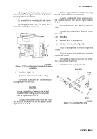
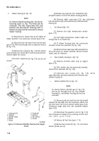
Figure
7-5.
Charging System.
7-8.
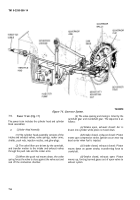
Governor System (Fig. 7-6)
a.
The
purpose of the engine governor is to maintain
a constant engine speed during changes in power
demands. The governor responds to changes in power
demands by varying the throttle position.
b.
The
constant-speed governor maintains engine
speed up to 2400 rpm. The speed-sensing device is a ball
and cup mechanism on the camshaft gear. A yoke, resting
on the cup, is connected to the governor arm which, in
turn, is connected to the throttle lever. Any change in
engine speed is transmitted from the cup to the yoke, and
then to the throttle.
c.
Tension on the governor spring determines the
speed at which the engine is governed. A stud screwed into
the spring is used to vary the number of effective cots for
getting the desired sensitivity-the speed drop from
no-load to full-load.
7-5
Back to Top

