TM-9-2330-356-14
SEMITRAILER, TANK: 5000 GALLON, BULK HAUL, SELF LOAD/UNLOAD M967 AND M967A1; SEMITRAILER, TANK: 5000 GALLON, FUEL DISPENSING, AUTOMOTIVE M969 AND M969A1; SEMITRAILER, TANK: 5000 GALLON, FUEL DISPENSING, UNDER/OVERWING AIRCRAFT M970 AND M970A1
TECHNICAL MANUAL; OPERATOR’S, UNIT, DIRECT SUPPORT, AND GENERAL SUPPORT MAINTENANCE MANUAL
OCTOBER 1990
TM-9-2330-356-14 - Page 370 of 528
TM 9-2330-356-14
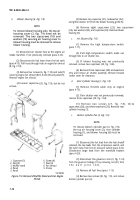
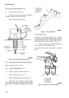
Figure 7-13. High Temperature Switch Installation.
7-18.
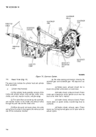
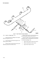
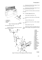
Governor Linkage (Fig. 7-1 4)
d.
Remove cotter pin (5), and remove throttle rod
(7) and two washers (20) from control arm (19).
a.
Disconnect governor linkage (1) from injector
e.
Remove bracket (12) from engine back plate by
pump (2) and governor arm (3).
removing two screws (13), lockwashers (14), and nuts (15).
Remove spring (17) and disconnect governor arm
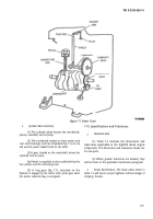
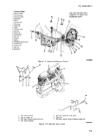
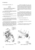
7-19. Fuel Lines (Fig. 7-15)
(3) from governor shaft (4).
a.
Tag and remove injector nozzle return lines (3).
Remove cotter pin (8) and clevis pin (9), and
b.
Remove manifold (4) and return line (5).
disconnect yoke (10) from throttle rod (7).
c.
Tag and remove injector lines (7).
7-14
Back to Top

