TM-9-2330-356-14
SEMITRAILER, TANK: 5000 GALLON, BULK HAUL, SELF LOAD/UNLOAD M967 AND M967A1; SEMITRAILER, TANK: 5000 GALLON, FUEL DISPENSING, AUTOMOTIVE M969 AND M969A1; SEMITRAILER, TANK: 5000 GALLON, FUEL DISPENSING, UNDER/OVERWING AIRCRAFT M970 AND M970A1
TECHNICAL MANUAL; OPERATOR’S, UNIT, DIRECT SUPPORT, AND GENERAL SUPPORT MAINTENANCE MANUAL
OCTOBER 1990
TM-9-2330-356-14 - Page 372 of 528
TM 9-2330-356-14
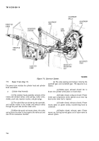
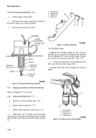
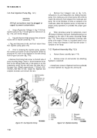
7-20. Fuel Stop Solenoid (Fig. 7-16)
a.
Remove engine shroud panel.
b.
Remove the two screws fastening the solenoid to
the bottom cylinder pan. Remove solenoid.
c.
Remove electrical lead to control.
Figure 7-16. Removal of Fuel Stop Solenoid.
7-21.
Engine Junction Box and Electrical Wiring
Refer to paragraph 4-19 for removal
7-22.
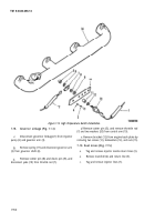
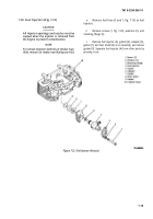
Exhaust Manifold (Fig. 7-17)
a.
Remove air shutter assembly (para 7-14).
b.
Remove exhaust pipe (para 4-77).
c.
Remove high temperature switch (para 7-17).
d.
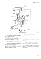
Bend tabs (1, fig. 7-17) down, and remove eight
capscrews (2) and washers (3) attaching exhaust manifold
(4) to cylinder heads. Remove manifold and four gaskets
(5).
Figure 7-17. Exhaust Manifold.
7-23. Oil Filler Tube
a.
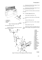
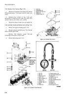
Remove the fuel filter adapter (1, fig. 7-18) and
fuel filters (2) as an assembly by removing three capscrews
(3) and lockwashers (4). Lower assembly enough to expose
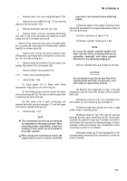
the two filler tube mounting capscrews (1, fig. 7-19).
b.
Remove two capscrews (1) and lockwashers (2)
that secure filler tube (3) to engine block.
c.
Remove filler tube (3) and gasket (4). Discard
gasket.
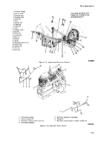
Figure 7-18. Removal of Fuel Filter Adapter
7-16
Back to Top

