TM-9-2330-356-14
SEMITRAILER, TANK: 5000 GALLON, BULK HAUL, SELF LOAD/UNLOAD M967 AND M967A1; SEMITRAILER, TANK: 5000 GALLON, FUEL DISPENSING, AUTOMOTIVE M969 AND M969A1; SEMITRAILER, TANK: 5000 GALLON, FUEL DISPENSING, UNDER/OVERWING AIRCRAFT M970 AND M970A1
TECHNICAL MANUAL; OPERATOR’S, UNIT, DIRECT SUPPORT, AND GENERAL SUPPORT MAINTENANCE MANUAL
OCTOBER 1990
TM-9-2330-356-14 - Page 368 of 528
TM 9-2330-356-14
b.
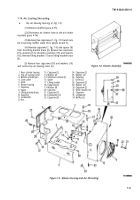
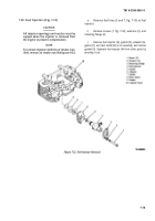
Blower Housing (6, Fig. 7-9).
NOTE
To remove blower housing only, the top air
housing cover (2, fig. 7-9) need not be
removed. The two capscrews (18) and
washers (19) securing air housing cover to
blower housing must be removed to remove
blower housing.
(1) Disconnect air cleaner hose at the engine air
intake manifold, if not previously removed (para 4-74).
(2) Disconnect the fuel hoses from the fuel tank
(para 4-73). Pull hoses through holes in engine fan shroud
(8, fig. 7-10).
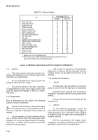
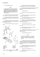
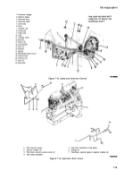
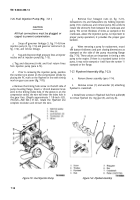
(3) Remove four screws (6, fig. 7-10) and nuts(7)
securing engine fan shroud (8) to frame (9) and panel (5).
Remove engine fan shroud.
(4) Loosen capscrew
remove.
(20, fig. 7-9), but do not
1. Capscrew (5)
6. Screw (4)
2. Nut (5)
7. Nut (4)
3. Muffler stand
8. Fan shroud
4. Panel
9. Frame
5. Panel
TA100C83
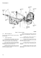
Figure 7-10. Removal of Muffler Stand and Fan Engine
Shroud.
(5) Remove top capscrew (21), lockwasher (22),
and grille retainer (31) from the blower housing grille (5).
(6) Remove eight capscrews (23), two capscrews-
(24), two washers (25), and capscrew (26). Remove blower
housing (6).
c.
Air Shutter (Fig. 7-8).
(1) Remove the high temperature switch
(para 7-17).
(2) Pull high temperature switch leads out
through hole in air shutter box.
(3) If blower housing was not previously
removed, remove two capscrews (29, fig. 7-44).
(4) Remove three capscrews (30) and washers
(31), and remove air shutter assembly. Remove forward
rocker cover for clearance.
d.
Rear Cylinder Housing (1, Fig. 7-9).
(1) Remove throttle cable only at engine
(para 4-75).
(2) If air shutter was not previously removed,
remove three capscrews (30, fig. 7-44).
(3) Remove two screws (27, fig. 7-9), three
capscrews (28), and three washers (29). Remove rear
cylinder housing (1).
e.
Bottom Cylinder Pan (3, Fig. 7-9).
NOTE
To remove bottom cylinder pan (3, fig. 7-9),
the top air housing cover (2), rear cylinder
housing (1), and blower housing (6) must be
removed.
(1) Disconnect the hot lead from the fuel shutoff
solenoid, the two leads from the oil pressure switch, and
the nylon tube from the oil pressure switch (para 4-22).
Disconnect large lead from the manifold heaters
(para 4-20).
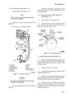
(2) Disconnect the governor arm (3, fig. 7-14)
from the governor linkage (1) by removing nut (21) from
the ball joint (22) .
(3) Remove all fuel lines (para
(4) Remove two screws (30, fig.
bottom cylinder pan (3).
7- 19).
7-9), and remove
7-12
Back to Top

