TM-9-2330-356-14
SEMITRAILER, TANK: 5000 GALLON, BULK HAUL, SELF LOAD/UNLOAD M967 AND M967A1; SEMITRAILER, TANK: 5000 GALLON, FUEL DISPENSING, AUTOMOTIVE M969 AND M969A1; SEMITRAILER, TANK: 5000 GALLON, FUEL DISPENSING, UNDER/OVERWING AIRCRAFT M970 AND M970A1
TECHNICAL MANUAL; OPERATOR’S, UNIT, DIRECT SUPPORT, AND GENERAL SUPPORT MAINTENANCE MANUAL
OCTOBER 1990
TM-9-2330-356-14 - Page 369 of 528
TM 9-2330-356-14
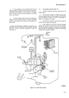
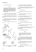
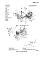
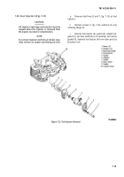
7-15. Oil Cooler and Lines (Fig. 7-11)
a.
Remove blower housing (para 7-14).
NOTE
Oil cooler and lines maybe filled with oil. Use
care to prevent spillage.
b.
Disconnect oil cooler hoses at valve of oil filter
adapter (11).
c.
Drain cooler into a suitable container.
1. Capscrew
7. Bracket
2. Clamp (2)
8. Hose
3. Capscrew (4)
9. Hose
4. Lockwasher (4)
10. Capscrew (2)
5 Nut (4)
11. Oil filter adapter
6. Oil cooler
TA100084
Figure 7-11. Oil Cooler and Lines.
CAUTION
Do not bend or damage the aluminum cooling
fins when removing cooler.
d.
Remove self-locking screw (1) and two retaining
clamps (2).
Remove four capscrews (3), lockwashers (4), and
nuts (5) attaching oil cooler (6) to mounting bracket (7),
and remove cooler.
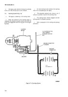
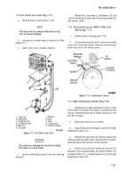
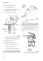
7-16. Tachometer Sensor (M967, M969, and
M970) (fig. 7-12)
a.
Remove blower housing (pars 7-14).
b.
Unscrew bottom jam nut on sensor and remove
sensor from mounting bracket. Disconnect two electrical
leads from sensor and remove sensor.
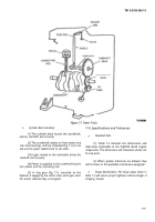
Figure 7-12. Tachometer Sensor
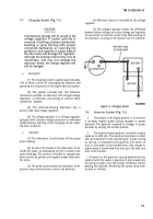
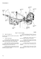
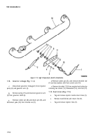
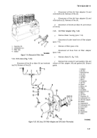
7-17. High Temperature Switch (Fig. 7-13)
a.
Replacement of high temperature switch is done
from under the vehicle. The switch is attached to the
exhaust manifold behind the air shutter assembly on the
left side of engine.
b.
Block open louvers on air shutter.
Tag and disconnect two leads (1 and 2) from high
temperature switch (13).
d.
Remove two capscrews (3) and two washers (4)
holding switch bracket (10) to the exhaust manifold.
Remove bracket with pressure switch attached.
Remove the nut (5), star washers (6), terminal (7),
flatwasher (8), insulated washer (9), switch bracket (10),
insulated sleeve (11), insulated washer (12), and high
temperature switch (13).
7-13
Back to Top

