TM-9-2330-356-14
SEMITRAILER, TANK: 5000 GALLON, BULK HAUL, SELF LOAD/UNLOAD M967 AND M967A1; SEMITRAILER, TANK: 5000 GALLON, FUEL DISPENSING, AUTOMOTIVE M969 AND M969A1; SEMITRAILER, TANK: 5000 GALLON, FUEL DISPENSING, UNDER/OVERWING AIRCRAFT M970 AND M970A1
TECHNICAL MANUAL; OPERATOR’S, UNIT, DIRECT SUPPORT, AND GENERAL SUPPORT MAINTENANCE MANUAL
OCTOBER 1990
TM-9-2330-356-14 - Page 338 of 528
TM 9-2330-356-14
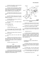
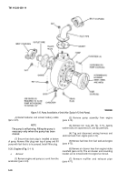
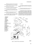
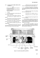
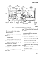
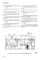
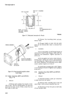
5-24. Hose Reel Assembly- 1¼-inch and 1 ½-inch
(Figs. 5-14 and 5-15)
a.
Removal.
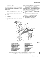
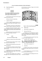
(1) Remove hose reel cabinet from semitrailer
(para 5-22).
(2) Remove hose assembly from hose reel using a
pipe wrench or spanner wrench (para 4-89).
(3) Remove cover on motor junction box. Tag and
disconnect electrical leads and conduit from motor
junction box.
(4) Remove split coupling to disconnect hose reel
from meter (M969 and M969A1) or gate valve P (M970
and M970A1).
(5) Remove mounting screws, washers, and nuts.
TWO people can then lift the hose reel from the cabinet.
b.
Installation.
(1) Have two people position hose reel in
cabinet. Install mounting screws, washers, and nuts.
Tighten nuts to 25-35 lb.-ft.
(2) Install split coupling (para 4-85). Tighten
coupling to 57-63 lb.-ft.
(3) Connect electrical leads and conduit to motor
junction box as tagged. Install cover on junction box.
(4) Install hose assembly on hose reel
(para 4-89).
(5) Install hose reel cabinet to semitrailer
(para 5-22).
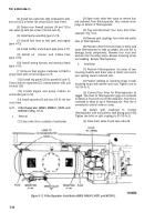
5-25. Meter Assembly (M969 and M969A1)
(Fig. 5-1 5)
a.
Removal.
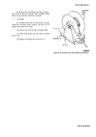
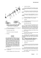
(1) Remove split couplings on meter inlet and
outlet lines. Slide the coupling gaskets towards the meter
to expose the joint in the piping.
(2) From under cabinet, remove three mounting
screws. Use a suitable lifting device and remove meter.
(3) Remove flanged connections from meter
inlet and outlet after meter is removed from cabinet.
Discard gaskets from flanges.
b.
Installation.
(1) Use new gaskets, and install flanged
connections on inlet and outlet ports of meter. Tighten
four nuts on each flange to 50-75 lb.-ft. Install gaskets for
split couplings.
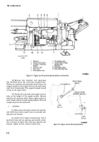
Figure 5-15. Hose Reel Cabinet Assembly, (M969 and M969A1) Roadside View.
5-30
Back to Top

