TM-9-2330-356-14
SEMITRAILER, TANK: 5000 GALLON, BULK HAUL, SELF LOAD/UNLOAD M967 AND M967A1; SEMITRAILER, TANK: 5000 GALLON, FUEL DISPENSING, AUTOMOTIVE M969 AND M969A1; SEMITRAILER, TANK: 5000 GALLON, FUEL DISPENSING, UNDER/OVERWING AIRCRAFT M970 AND M970A1
TECHNICAL MANUAL; OPERATOR’S, UNIT, DIRECT SUPPORT, AND GENERAL SUPPORT MAINTENANCE MANUAL
OCTOBER 1990
TM-9-2330-356-14 - Page 66 of 528
TM 9-2330-356-14
(5)
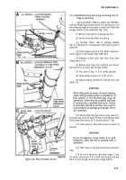
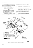
Put selector valve E (fig. 2-11) in LOAD
position (M967, M967A1, M969, and M969A1).
(6)
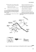
Open emergency valve operator A (fig. 2-11
or 2-12) (para 2-11f).
(7)
Begin flow.
WARNING
When filling tank by means of bottom loading,
a test of the precheck system is mandatory. If
this system is not functioning, stop all
operations. Determine the problem and have
It corrected by a qualified technician. Failure
of automatic shut-off to function may result In
uncontrolled fuel spillage and danger of fire
and explosion.
(8)
After flow has begun, open valve D to
precheck the shut-off float (para 2-11g). If float is
functional, flow should stop after about 20-25 seconds.
(9)
Close valve D. Flow will resume in about 20
seconds.
NOTE
Be prepared to stop the fuel supply at the
loading facility in event of shut-off float
malfunction, if leaks are apparent, or other
unusual conditions are seen.
(10)
When tank is full, the flow should stop
automatically. Close all valves, replace all covers, and
disconnect the hoses.
(11)
(12)
(13)
Drain accumulated water (para 2-13d).
Remove grounding wires.
Store and cover fire extinguishers.
c.
Gravity Unload.
(1)
Review instructions in paragraph 2-8.
(2)
Ensure that all valves are closed.
(3)
Connect grounding wire to storage facility
and grounding stud (fig. 2-7) on top of semitrailer.
(4)
Remove 4-inch bulk delivery hose(s) from
trough (fig. 2-20) by disconnecting spring pins and turning
hose trough bars out of the way.
(5)
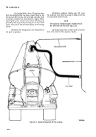
Remove dust cover from outlet B (figs. 2-23
and 2-11 or 2-12), and connect hose to outlet B and to
storage facility.
(6)
Remove fire extinguishers and bring to point
of operation.
(7)
Make sure valve E (fig. 2-11) (M967,
M967A1, M969, and M969A1) is in the UNLOAD
position.
(8)
Open valves A (para 2-11f), H, G, and B
(fig. 2-11 or 2-12) to begin flow.
(9)
At end of operation, close all valves.
Disconnect the hose and put it in hose trough; secure hose
trough latches. Reinstall dust cover on outlet B.
(10)
Drain accumulated water (para 2-13d).
(11)
Remove grounding wires.
(12) Store and cover fire extinguishers.
d.
Water Drain.
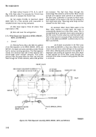
Accumulated water should be
drained from the system after each period of operation
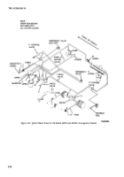
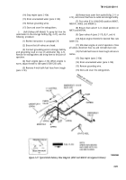
(fig. 2-24).
(1)
Ensure that all valves are closed.
(2)
Put a container under manifold drain in
piping control cabinet. Open emergency valve operator A.
Slowly open valves H and J. Allow to drain until pure fuel
begins to flow. Close valves H and J, and emergency valve
operator A.
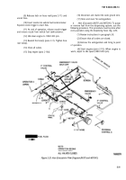
(3)
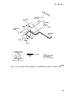
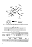
Drain the pilot lines on all models. Open
drain valves as indicated in figure 2-25. Allow to drain until
fuel begins to flow. Close drain valves.
(4)
On models M969, M969A1, M970, and
M970A1, also drain the filter/separator. Open valve M.
Put a container under valve N on bottom of
filter/separator. Slowly open valve N. Allow to drain until
fuel begins to flow. Close valves N and M.
2-24
Back to Top


