TM-9-2330-356-14
SEMITRAILER, TANK: 5000 GALLON, BULK HAUL, SELF LOAD/UNLOAD M967 AND M967A1; SEMITRAILER, TANK: 5000 GALLON, FUEL DISPENSING, AUTOMOTIVE M969 AND M969A1; SEMITRAILER, TANK: 5000 GALLON, FUEL DISPENSING, UNDER/OVERWING AIRCRAFT M970 AND M970A1
TECHNICAL MANUAL; OPERATOR’S, UNIT, DIRECT SUPPORT, AND GENERAL SUPPORT MAINTENANCE MANUAL
OCTOBER 1990
TM-9-2330-356-14 - Page 75 of 528
TM 9-2330-356-14
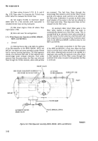
(b) As
water accumulates in the filter sump
of the M970 and M970A1, a float rises. When the float
rises a certain level, a valve will open in the automatic
drain valve, allowing pump pressure to be applied to a
diaphragm valve in the automatic drain valve and to the
pilot control on the 3-inch flow control valve. The pump
pressure opens the diaphragm valve and closes the 3-inch
flow control valve. Fuel flow is then shut off, preventing
dispensing of water-contaminated fuel, and the water in
the filter sump is passed through the automatic drain
valve. When the fuel flow is stopped by the closing of the
3-inch flow control valve, no coalescing occurs, and the
automatic water drain valve will continue passing water
until the float lowers. With the float in the lowered
position, the water drain valve closes, and the 3-inch
control valve opens. When this happens, pressure is
trapped in the line to the automatic drain valve diaphragm
and pilot control of the 3-inch control valve, preventing
resumption of fuel flow. To release the pressure, a bleed
line from the automatic drain valve diaphragm and pilot
control will relieve the pressure at the discharge side of
the water drain valve. Fuel flow will automatically start
again.
(3)
Cold Weather Draining.
During cold weather
operations, the accumulated water in the sump may
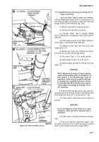
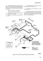
freeze. It is important that the manual drain N (fig. 2-30)
on the sump be opened after each operation to drain the
water accumulation. Be sure to close the drain valve after
draining.
(4)
Go-No-Go Fuses.
Each of the 5 second-stage
coalescing elements is equipped with three Go-No-Go
fuses. These fuses are fuel contaminant monitoring
devices located “down-stream” of the second-stage. The
fuses restrict the fuel flow when small amounts of water
and solid contaminants are present in the fuel stream.
(a)
Each fuse consists of a perforated metal
tube filled with thin cellulose washers, except for a space
about l-inch long at one end. This space is for a plastic
piston forced against the washers by a spring. A plastic
nipple at the other end of the metal tube fits into an outlet
socket in the housing. Fuel flow is through the spirally
arranged perforations in the metal tube. The fuel must
flow through the very small passages (about 5 microns)
between the cellulose washers to reach the outlet.
(b)
As solid contaminants accumulate on
the outer surface of the stack of washers, resistance to fuel
flow increases. The resulting increased pressure further
compresses the washer stack. When the contaminant is
water, it is also absorbed by the cellulose washers, and the
action of the filter is similar.
(c)
When solid contaminants or water are
present, the compression of the washer stack continues
until fuel flow is stopped completely. But until this
happens, whatever fuel is passed through is still within the
specified standards for purity.
b.
Filter/Separator Gage. The
filter elements have a
limited capacity for retaining solids. As the solids content
increases, a pressure drop across the elements increases.
The pressure drop can be measured by a pressure gage
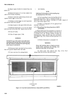
provided in the instrument panel (fig. 2-9). Operating
pressure readings should be taken and recorded at the first
day of operation and each day of operation thereafter. At
initial operation or with replacement elements, the
pressure gage reading should not exceed 3 psi. When the
pressure gage reading reaches 25 psi, the elements are
dirty and should be replaced. Notify unit maintenance
personnel when pressure reaches 25 psi.
2-16. Filtered Fuel Servicing Operations (M969
and M969A1)
a.
Filtered Bulk Delivery.
This operation is to be used
when filtered fuel is required in the storage facility
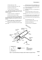
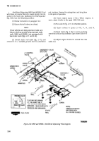
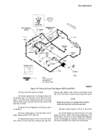
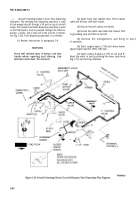
(fig. 2-31). Fuel is pumped from the semitrailer tank
through the filter/separator to the storage facility.
Filtered bulk delivery operation is as follows:
(1) Review instructions in paragraph 2-8.
(2) Ensure that all valves are closed.
(3) Connect grounding wire to storage facility
and semitrailer (fig. 2-7). Remove 4-inch bulk fuel hose
(para 2-13) from hose trough and connect it to the
receiving facility. Remove dust cap from outlet B and
connect bulk fuel hose to outlet.
(4) Remove fire extinguishers and bring them to
the point of operation.
(5) Start engine (para 2-10) and when warm
adjust engine speed to 1000-1200 rpm.
(6)
(7)
(8)
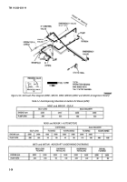
(table 2-2).
(9)
Put selector valve E in UNLOAD position.
Open valves A (para 2-11f), B, H, M, and K.
Adjust engine throttle for desired flow rate
At end of operation, adjust engine to idle
speed (1000-1200 rpm).
(10) Close all valves.
(11) Remove all hoses and store in hose troughs.
Secure hose trough latches. Reinstall dust cover on outlet
B.
(12) Shut off engine (para 2-10d).
(13) Remove grounding wire.
(14) Cover and store fire extinguishers.
2-33
Back to Top

