TM-9-2330-356-14
SEMITRAILER, TANK: 5000 GALLON, BULK HAUL, SELF LOAD/UNLOAD M967 AND M967A1; SEMITRAILER, TANK: 5000 GALLON, FUEL DISPENSING, AUTOMOTIVE M969 AND M969A1; SEMITRAILER, TANK: 5000 GALLON, FUEL DISPENSING, UNDER/OVERWING AIRCRAFT M970 AND M970A1
TECHNICAL MANUAL; OPERATOR’S, UNIT, DIRECT SUPPORT, AND GENERAL SUPPORT MAINTENANCE MANUAL
OCTOBER 1990
TM-9-2330-356-14 - Page 74 of 528
TM 9-2330-356-14
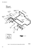
(5) Open valves A (para 2-11f), E, G, and K
(fig. 2-29). Open valve P to evacuate the 1½-inch hose
and/or valve R to evacuate the 2½-inch hose.
(6) Set engine throttle to maximum speed
(2400 rpm) for a few seconds until evacuation is
completed (meter stops turning backward).
(7) Idle down engine. Close all valves. Stop
engine (para 2-10d).
(8) Store and cover fire extinguishers.
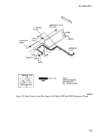
2-15. Filter/Separator Operation (M969, M969A1,
M970, and M970A1)
a.
General.
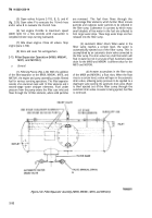
(1)
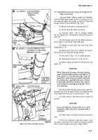
Filtering Process (Fig, 2-30).
With the addition
of the filter/separator on the M969, M969A1, M970, and
M970A1, the engine and pump assembly provides filtered
fuel for various servicing operations. The filter/separator
consists of an aluminum tank with 15 filter elements and 5
second-stage water stripper elements. Fuel under
pressure from the pump enters the filter case inlet and
flows through the 15 filter elements, where solid particles
are removed.
The fuel then flows through the
second-stage filter elements, which further filters minute
particles and coalesces water particles to be collected in
the filter sump. Coalescence is a process by which many
small droplets of free water in the fuel are collected to
form larger water drops. These large water drops are then
released into the filter sump.
(2)
Automatic Water Drain.
When water in the
filter sump reaches a certain level, the water is
automatically ejected out of the filter sump. This is
accomplished by an automatic drain valve connected to
the filter sump. The drain valve has a ball float which will
float in water but not in any type of fuel. Automatic water
drain for the M969 and M969A1 is different than for the
M970 and M970A1.
(a) As
water accumulates in the filter sump
of the M969 and M969A1, a float rises. When the float
rises to a certain level, a valve will open in the automatic
drain valve, allowing pump pressure to be applied to a
diaphragm valve opening the automatic drain valve. Water
is then ejected out of the filter sump through the
automatic drain valve. As water is being ejected, fuel flow
is continued.
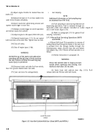
Figure 2-30. Filter/Separator Assembly (M969, M969A1, M970, and M970A1).
2-32
Back to Top

