TM-9-2350-260-20-1-2 - Page 129 of 772
TM 9-2350-260-20-1-2
CYLINDER HEAD AND OIL PAN DRAIN TUBES (LEFT AND RIGHT) REPLACEMENT (Sheet 1 of 4)
PROCEDURE INDEX
PROCEDURE
PAGE
Removal
6-52
Inspection
6-53
Installation
6-54
TOOLS:
7/8 in. socket with 1/2 in. drive
Diagonal cutting pliers
Flat-tip screwdriver
Slip joint pliers
1/2 in. socket with 1/2 in. drive
3/8 in. combination box and open end wrench
Ratchet with 1/2 in. drive
SUPPLIES:
Lockwire (Item 59, Appendix D)
Gasket (8682772)
Lockwasher (7410218) (2 required)
SPECIAL TOOLS: Ground hop kit (Item 32, Chapter 3, Section D
REFERENCE: LO 9-2350-260-12
PRELIMINARY PROCEDURE: Remove powerplant (page 5-1)
Drain engine oil (2A engine, page 6-47) (2D engine, page 6-49)
Remove powerplant left bank oil cooler frame and brackets (2D engine, page 6-108) (as
required)
Remove powerplant right bank oil cooler frame and brackets (2D engine, page 6-99) (as
required)
Remove powerplant oil coolers frame and brackets (2A engine, page 6-94)
REMOVAL:
1.
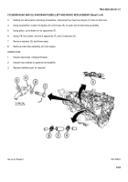
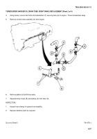
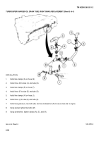
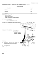
Using 1/2 inch socket, remove two bolts and lockwashers (A).
Throw lockwashers away.
2.
Remove gasket (B) and throw away.
Go on to Sheet 2
TA147506
6-52
Back to Top


