TM-9-2350-260-20-1-3 - Page 120 of 783
TM 9-2350-260-20-1-3
MASTER CONTROL PANEL REPAIR (Sheet 46 of 71)
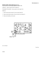
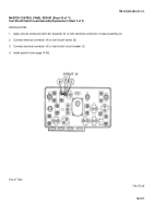
Bilge Pump Switch Lead Assembly and Power Connector Assembly Replacement
(Sheet 1 of 2)
SUPPLIES:
Silicone compound (Item 32, Appendix D)
PRELIMINARY PROCEDURE:
Remove panel from tank (page 10-54)
NOTE
This procedure is used only when a bilge pump switch is present
REMOVAL:
1.
Remove electrical lead connector (A) circuit 451 from bilge pump switch (B).
2.
Remove electrical lead connector (A) from power connector (C) by pulling apart.
3.
Disconnect power connector (C) and gas particulate switch lead connector (D) circuit 415 by pulling apart.
4.
Disconnect power connector C) and bilge pump circuit breaker lead connector (E) circuit 920 by pulling apart.
5.
Remove wiring harness (A) from panel.
Go on to Sheet 2
TA147140
10-108
Back to Top


