TM-9-2350-260-20-1-3 - Page 723 of 783
TM 9-2350-260-20-1-3
TRACK ASSEMBLY REPLACEMENT (Sheet 10 of 10)
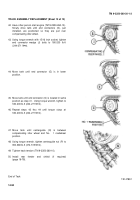
42. Have other person start engine (TM 9-2350-260-10).
Slowly drive tank until end connectors (G), just
installed, are positioned so they are just over
compensating idler wheel.
43. Using torque wrench with 15/16 inch socket, tighten
end connector wedge (J) bolts to 180-200 lb-ft
(244-271 N
•
m).
44. Move tank until end connector (G) is in lower
position.
45. Move tank until end connector (G) is located in same
position as step 41.
Using torque wrench, tighten to
180-200 lb-ft (244-271 N
•
m).
46. Repeat steps 42 thru 44 until torque stays at
180-200 lb-ft (244-271 N
•
m).
47. Move tank until centerguide (N) is between
compensating idler wheel and No.
1 roadwheel
position.
48. Using torque wrench, tighten centerguide nut (P) to
350-380 lb-ft (474-515 N
•
m).
49. Tighten track tension (TM 9-2350-260-10).
50. Install rear fender and shield (if required)
(page 16-78).
End of Task
TA147891
14-90
Back to Top


