TM-9-2350-261-20-2 - Page 787 of 1008
TM 9-2350-261-20-2
REPLACE TORSION BAR ANCHOR — Continued
0386 00
3.
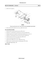
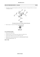
On all other carriers and torsion bar positions, install two pins (4) in anchor (2). Secure pins with two new cotter pins
(5). Bend pins as shown.
NOTE
Cotter pins must not prevent 360 degree rotation of anchor pins.
4.
Bend cotter pins (1) so they allow 360 degree rotation of anchor pins.
FOLLOW-THROUGH STEPS
1.
Install torsion bar (WP 0385 00).
2.
Install power plant for second torsion bar anchor, right side only (WP 0131 00).
3.
Install road wheel (WP 0371 00) (T130) or (WP 0372 00) (T150).
4 .
Road test carrier to check that torsion bar anchor is installed properly (WP 0120 00).
5.
Stop/shutdown engine (see your -10).
END OF TASK
0386 00-3/4 blank
Back to Top


