TM-9-2350-261-20-2 - Page 791 of 1008
TM 9-2350-261-20-2
ADJUST STEERING LINKAGE
0387 00
THIS WORK PACKAGE COVERS:
Adjustment (page 0387 00-1).
INITIAL SETUP:
Maintenance Level
Unit
Tools and Special Tools
General Mechanic’s Tool Kit (WP 0780 00, Item 29)
Materials/Parts
Cotter pin (2)
Screw 3/8-16 x 2-1/2 (2)
Personnel Required
Unit Mechanic
Helper (H)
References
WP 0185 00
WP 0390 00
Equipment Condition
Engine stopped/shutdown (see your -10)
Carrier blocked (see your -10)
Ramp lowered (see your -10)
Trim vane lowered (see your -10)
Power plant front access door open (see your -10)
Driver’s power plant access cover removed
(WP 0430 00)
ADJUSTMENT
NOTE
In most cases, adjustment of differential brake linkage is necessary only when a component of
the control linkage has been repaired or replaced.
1.
Remove air cleaner housing and element (WP 0185 00).
2.
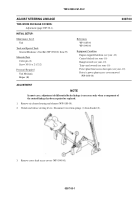
Unlock and release steering levers. Disconnect two return springs (1) from bracket (2).
3.
Remove cross-shaft access covers (WP 0390 00).
038700-1
Back to Top


