TM-9-2350-261-34 - Page 279 of 785
TM 9-2350-261-34
REPLACE FRONT MAIN WIRING HARNESS — Continued
0032 00
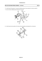
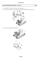
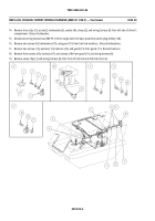
38. Route front main wiring harness (21) up behind instrument panel. Follow Steps 39 - 49 to attach leads to panel.
39. Connect circuit 406 lead (20) to air box heater switch.
40. Connect circuit 33 lead (19) to engine coolant temperature gauge.
41. Connect circuit 74 and 14 plug (18) to starter switch.
42. Connect circuit 516A lead (17) to infrared (I.R.) power selector switch.
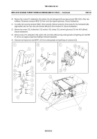
43. Connect circuit 15 lead (13), circuit 25A lead (14), circuit 27F lead (15), and circuit 14 lead (16) to instrument panel
wiring harness.
44. Connect circuit 19 lead (10), circuit 520 lead (11), and circuit 514-515 lead (12) to infrared blackout (I.R. - B.O.) switch.
NOTE
Step 44 applies to M1064 only.
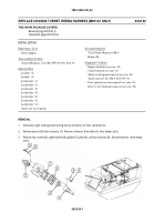
45. Install circuit 28 lead (18), circuit 30 lead (19), and circuit 31 lead (20) on fuel tank switch (21).
0032 00-22
Back to Top


