TM-9-2350-277-20-5 - Page 888 of 1047
TM 9-2350-277-20-5
REPAIR/REPLACE DRIVER’S DISPLAY ASSEMBLY (MFCS)
(M1064A3 ONLY)
0812 10
THIS WORK PACKAGE COVERS:
Removal (page 0812 10-1).
Disassembly (page 0812 10-2).
Repair (page 0812 10-3).
Assembly (page 0812 10-4).
Installation (page 0812 10-6).
INITIAL SETUP:
Maintenance Level
Unit
Tools and Special Tools
Electronic Equipment Tool Kit (WP 0926 00, Item 66)
Shop Set, Small Arms (WP 0926 00, Item 46.1)
Materials/Parts
Gasket
Lockwasher (12) (See TM 9-1220-248-23&P)
Self-locking nut (4)
Personnel Required
Mechanic
References
TM 9-1220-248-23&P
TM 9-2350-277-24P
REMOVAL
CAUTION
To prevent damage to equipment, ensure power is removed from system before driver’s display
(DD) is removed.
1.
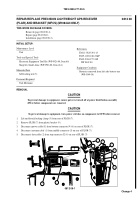
Disconnect power/data cable 3W1 (1) from J1 connector (2) on driver’s display (DD) (3).
2.
Remove socket head capscrew (9), lockwasher (4), and loop clamp (5) to free power/data cable 3W1 (1). Replace
hardware on driver’s display (3).
3.
Loosen locking handle (8) on ram arm (6). Remove DD (3) with ram arm from ball (7).
081210-1
Change 5
Back to Top


