TM-9-2350-277-20-5 - Page 893 of 1047
TM 9-2350-277-20-5
REPAIR/REPLACE DRIVER’S DISPLAY ASSEMBLY (MFCS) (M1064A3
ONLY) — Continued
0812 10
INSTALLATION
1.
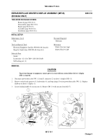
Install ram arm (6) with DD (3) on ball (7). Tighten locking handle (8).
2.
Remove socket head capscrew (9), lockwasher (4), and loop clamp (5) from DD (3). Place loop clamp around
power/data cable 3W1 (1) and secure to DD (3) with lockwasher and socket head capscrew.
CAUTION
To prevent damage to equipment, ensure power is removed from system before connecting cable
to driver’s display (DD).
3.
Connect power/data cable 3W1 (1) to J1 connector (2) on DD (3).
END OF TASK
0812 10-6
Change 5
Back to Top


