TM-9-2350-277-20-5 - Page 892 of 1047
TM 9-2350-277-20-5
REPAIR/REPLACE DRIVER’S DISPLAY ASSEMBLY (MFCS) (M1064A3
ONLY) — Continued
0812 10
6.
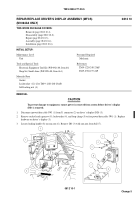
Remove 10 screws (11) and electrical box lid (12) in driver’s compartment.
NOTE
If driver’s display bracket is being installed in vehicle for the first time, proceed with Step 7. If
driver’s display bracket is being installed in previously-modified vehicle
,gotoStep9
.
7.
Position ball (7) near corner of electrical box lid (12) approximately 2 in. (5.1 cm) from each side. Using ball as a
template, mark position for four holes (31). Remove ball.
WARNING
Metal chips and grinding dust can cause eye injury. Wear goggles and gloves.
8.
Using drill and 1/4 in. (0.64 cm) drill bit, drill four through holes (31) in electrical box lid (12).
9.
Position ball (7) and new gasket (14) on electrical box lid (12) and align holes.
10. Install four socket head screws (10) and new self-locking nuts (13).
11. Install electrical box lid (12) and 10 screws (11).
081210-5
Change 5
Back to Top


