TM-9-2350-277-34 - Page 694 of 871
TM 9-2350-277-34
REPAIR POWER ENTRY BOX ASSEMBLY A4 (M1068A3 ONLY)
0095 00
THIS WORK PACKAGE COVERS:
Disassembly (page 0095 00-1).
Assembly (page 0095 00-3).
INITIAL SETUP:
Maintenance Level
Direct Support
Tools and Special Tools
General Mechanic’s Tool Kit (WP 0120 00, Item 62)
Materials/Parts
Locknut (8)
Lock washer
Personnel Required
Power-Generation Equipment Repairer 52D10
References
See your -20
Equipment Condition
Power entry box removed (see your –20)
DISASSEMBLY
1.
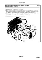
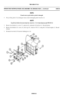
Open lid (1) to access faceplate (2).
2.
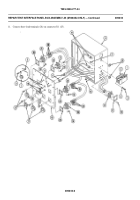
Remove six screws (3), washers (4), and faceplate (2) from power entry box (5).
3.
Remove four screws (6), cap and chain (7), locknuts (8), and cable W14 (9) from AC POWER OUT hole on faceplate
(2). Discard locknuts.
4.
Remove four screws (10), cap and chain (11), locknuts (12), and cable W13 (13) from EXTERNAL POWER IN hole on
faceplate (2). Discard locknuts.
0095 00-1
Back to Top


