TM-9-2350-277-34 - Page 685 of 871
TM 9-2350-277-34
REPLACE INVERTER AND INVERTER HOUSING ASSEMBLY A2 (M1068A3
ONLY) (OUTBACK ONLY) — Continued
0094 01
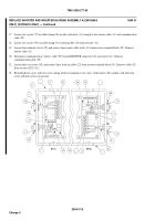
14. Loosen four set screws (58) on inverter terminal block (59). Route four leads on remote control cable (11) through cable
clamp (56) and attach to inverter terminal block (59). Tighten four set screws (58).
15. Install communication “comm” cable (55) through cable clamp (56) and attach to MATE/HUB (54) connector.
CAUTION
Do not over tighten cable clamp screws. Failure to comply may cause damage to wiring cable.
16. Tighten two screws (57) on cable clamp (56) securing one side of remote control cable (11) and “comm” cable (55) to
inverter (31).
Inverter Terminal
Cable Lead
INVERTER
GREEN
ON/OFF
WHITE
AUX +
RED
AUX -
BLACK
0094 01-18
Change 5
Back to Top


