TM-9-2350-311-20-2 - Page 438 of 828
TM 9–2350–311–20–2
8–14
8–2
GUNNER’S SELECTOR SWITCH BOX WIRING HARNESS — CONTINUED
a.
Removal — Continued
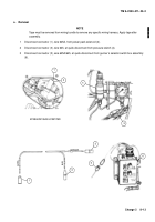
4
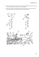
Remove three cap screws (7), three flat washers (8), three plastic attaching straps (9), and three lock-
washers (10) securing gunner’s selector switch box wiring harness (11) to vehicle. Discard lockwashers.
b.
Disassembly/Assembly
See repair procedures for harnesses, plugs, and terminals (para 8–1).
c.
Testing
Using multimeter, test gunner’s selector switch box wiring harness for continuity through all plugs and con-
nectors.
d.
Installation
1
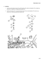
Secure gunner’s selector switch box wiring harness (11) to vehicle using three new lockwashers (10), three
plastic attaching straps (9), three flat washers (8), and three cap screws (7).
2
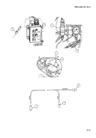
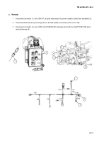
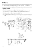
Connect connector (5), wire 625/645, at quick-disconnect from gunner’s selector switch box assembly (6).
3
Connect connector (3), wire 645, at quick-disconnect from pressure switch (4).
4
Connect connector (1), wire 625A, to power pack solenoid (2)
7
8
9
10
11
Back to Top


