TM-9-2520-215-34 - Page 254 of 508
TM 9--2520--215--34
0049 00--6
OUTPUT REDUCTION GEAR BRAKE HUB ASSEMBLY REPLACEMENT –
CONTINUED
0049 00
INSTALLATION – Continued
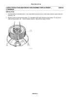
NOTE
Cam ring may be rotated to proper position after it is fully seated.
Illustration is for left output reduction gear assembly. Indexing notch
for right assembly would be aligned with fifth roller, counterclockwise
scribe mark.
5. Install 30 long rollers (9) and 15 short rollers (10). Moving rotating cam ring (15) until indexing notch (17) is
approximately in line with fifth long roller (9), counterclockwise from scribe mark.
Back to Top


