TM-9-2520-246-34-1 - Page 299 of 418
TM 9-2520-246-34-1
2.
o.
Companion Flanges.
FRAME 1
Soldier A
Soldier B
1.
3.
4.
5.
6.
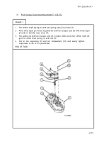
Push in shifter shaft (l).
Put deflector (2) and companion flange (3) on rear output shaft (4).
Using adjustable wrench as shown, hold companion flange (2).
Put on washer (5) and
GO TO FRAME
2
pound-feet.
Tighten slotted nut (6)
output shaft (4) .
Put in cotter pin (7).
slotted nut (6) and tighten nut to 300 to 400
until slot is alined with cotter pin hole in rear
2-279
Back to Top


