TM-9-2520-270-34 - Page 610 of 933
TM 9-2520-270-34
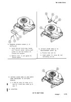
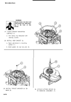
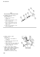
CHECK SHOULDERED SHAFT (1).
a. Using micrometer caliper set, meas-
ure diameter (2). Replace shaft (1)
if measurement is less than
0.7490 inch (19.025 mm).
b. Using micrometer caliper set, meas-
ure diameter (3). Replace shaft (1)
if measurement is less than
0.9990 inch (25.375 mm).
NOTE
Rod end connector (8) has left-hand threads.
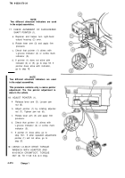
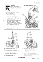
10. DISASSEMBLE ROD END CLEVIS (4)
AND ADJUSTER (5).
a.
b.
c.
d.
Remove and discard cotter pin (9).
Remove pin (10) from clevis (4).
Loosen hexagon nut (11) and remove
two rod end connectors (8) and (12)
from adjuster (5).
Remove nut (11) from rod end
connector (12).
NOTE
All brake adjuster screws do not use Iockwire.
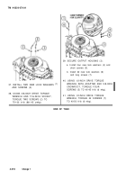
9. REMOVE ROD END CLEVIS (4)
AND BRAKE ADJUSTER (5).
a. Remove and discard Iockwire (6),
if used, from two screws (7).
b. Using 3/8-inch drive brace handle and
1/4-inch socket wrench attachment,
remove two screws (7).
c. Remove clevis (4) with adjuster (5)
GO TO NEXT PAGE
Change 2
4-281
Back to Top

