TM-9-2520-272-40 - Page 310 of 620
TM 9-2520-272-40
0039
INSTALL CONVERTER ELEMENT COMPONENTS
NOTE
Make sure that the transmission is on maintenance stand so that the input housing points up.
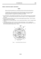
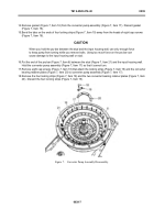
1. Install two 5/16-24 x 3 inch guide pins (Figure 10, Item 28) 180 degrees apart in the shoulder of the input
pump drive gear (Figure 10, Item 29).
2. Install new converter pump gasket (Figure 10, Item 26) over the guide pins (Figure 10, Item 28) and on the
shoulder of the input pump drive gear (Figure 10, Item 29).
NOTE
You will not be able to see the manufacturer’s balance mark after you install the converter
pump. Using a black marker, put a mark at the location of the balance mark near a stud so
that you can see it from the top view of the converter pump.
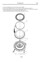
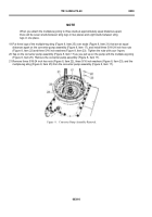
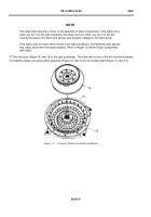
3. Install the converter pump assembly (Figure 10, Item 17) over guide pins (Figure 10, Item 28).
NOTE
Make sure the converter pump assembly is down far enough to allow the inner lips on the
converter bearing retainer plate to touch and align with groove on bearing.
4. Tap the converter pump assembly (Figure 10, Item 17) to install the pump on gasket (Figure 10, Item 26).
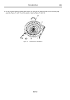
5. Remove two guide pins (Figure 10, Item 28).
0039
‐
10
Back to Top

