TM-9-2520-272-40 - Page 307 of 620
TM 9-2520-272-40
0039
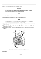
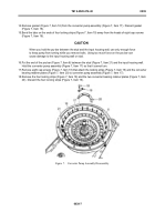
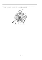
14.Remove gasket (Figure 7, Item 16) from the converter pump assembly (Figure 7, Item 17). Discard gasket
(Figure 7, Item 16).
15.Bend the tabs on the ends of four locking strips (Figure 7, Item 19) away from the heads of eight cap screws
(Figure 7, Item 18).
CAUTION
When you hold the pry bar between the stud and the input housing wall, use only enough force
to keep pump from turning while you remove bolts. Using too much force on the pry bar can
cause damage to the input housing wall or stud.
16.Put the end of the pry bar (Figure 7, Item 6) between the stud (Figure 7, Item 21) and the input housing wall.
Hold the converter pump assembly (Figure 7, Item 17) so that it cannot turn.
17.Remove eight cap screws (Figure 7, Item 18) that attach the locking strips (Figure 7, Item 19) and the converter
bearing retainer plates (Figure 7, Item 20) to converter pump assembly (Figure 7, Item 17).
18.Remove the four locking strips (Figure 7, Item 19) and the two converter bearing retainer plates (Figure 7, Item
20). Discard the four locking strips (Figure 7, Item 19).
Back to Top


