TM-9-2520-272-40 - Page 313 of 620
TM 9-2520-272-40
0039
NOTE
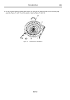
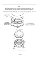
The two locking plates go over the two bolt holes on the retainers.
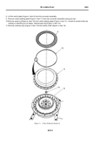
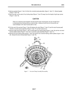
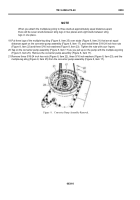
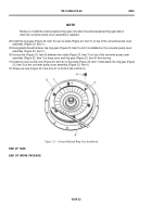
7. Place four new locking strips (Figure 12, Item 19) on the converter bearing retainer plates (Figure 12, Item
20), bent tabs up.
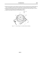
8. Install eight cap screws (Figure 12, Item 18) in locking strips (Figure 12, Item 19) and converter bearing
retainer plates (Figure 12, Item 20).
9. Use a pry bar to keep the converter pump assembly (Figure 12, Item 17) from turning. Torque eight cap screws
(F
igure12
,I
tem18)to19to23lb-
f
t(25to31N·m)
.Removeprybar
.
Back to Top


