TM-9-2520-272-40 - Page 314 of 620
TM 9-2520-272-40
0039
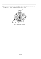
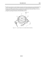
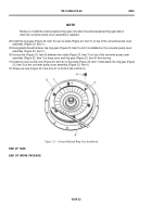
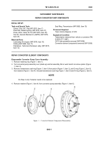
10.Bend all eight tabs of locking strips (Figure 13, Item 19) at ends of four converter bearing retainer plates (Figure
13, Item 20) so that tabs are against f ats of cap screws (Figure 13, Item 18).
NOTE
Do not lubricate the 13.750 in. (349.25 mm) Inside Diameter (ID) gasket installed in the next
step.
11. Install new gasket (Figure 13, Item 16) in groove near pump studs (Figure 13, Item 21).
Back to Top

