TM-9-2520-272-40 - Page 381 of 620
TM 9-2520-272-40
0045
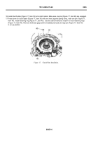
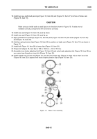
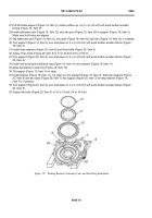
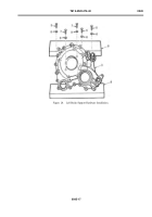
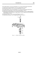
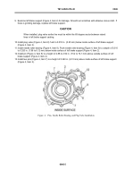
48.Turn support (Figure 22, Item 3) over and place on 2 x 4 x 24 inch soft wood lumber wooden blocks.
49.Install eight balls (Figure 22, Item 20) into lowest areas of ramps on stationary cam (Figure 22, Item 12).
50.Apply petrolatum to balls (Figure 22, Item 20) and in ramps around balls.
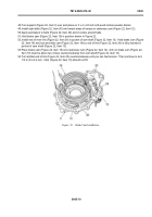
51.Hold brake cam (Figure 22, Item 19) in position shown in Figure 22.
52.Install end of inner link (Figure 22, Item 24) in pocket of cam shaft (Figure 22, Item 13). Hold brake cam (Figure
22, Item 19) and turn and twist cam (Figure 22, Item 19) so end of link (Figure 22, Item 24) is fully inserted in
pocket of cam shaft (Figure 22, Item 13).
53.Place brake cam (Figure 22, Item 19) onto stationary cam (Figure 22, Item 12). Arm on brake cam (Figure 22,
Item 19) must be about two inches counterclockwise from cam shaft (Figure 22, Item 13).
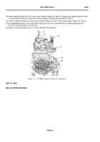
54.Turn slotted end of link (Figure 22, Item 25) counterclockwise until you can feel tension. Then continue to turn
1/2 to 3/4 of a turn. Cam (Figure 22, Item 19) should not lift.
Back to Top


