TM-9-2520-272-40 - Page 373 of 620
TM 9-2520-272-40
0045
INSTALL LEFT BRAKE ASSEMBLY
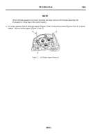
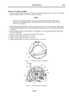
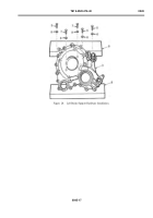
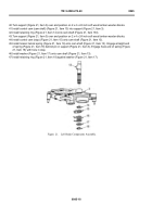
1. Install six headless straight pins (Figure 13, Item 46) in brake backing plate (Figure 13, Item 47). Wind rubber
bands around pins (Figure 13, Item 46) to hold them in position.
NOTE
When you remove rubber bands from six pins, one pin (shown bottom right in Figure 13) will
drop down. To help with assembly, a thickness gage (shim) must be positioned under the pin to
retain it in an up position.
2. Install brake backing plate (Figure 13, Item 47), along with pins (Figure 13, Item 46). Remove rubber bands
and put thickness gage blade (shim) under bottom left pin to keep pin (Figure 13, Item 46) up until assembly
is complete.
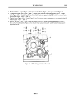
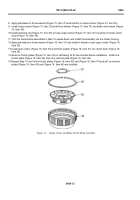
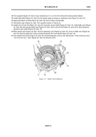
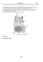
3. Install f ve washers (Figure 14, Item 44) and f ve bolts (Figure 14, Item 43) that keep backing plate (Figure
14, Item 47) in position.
4. Torque f ve bolts (Figure 14, Item 43) to 36 to 43 lb-ft (49 to 68 N·m).
5. Install new brake coolant seal (Figure 14, Item 45).
6. Install four brake reaction pins (Figure 14, Item 34).
7. Install six springs (Figure 14, Item 42) over six pins (Figure 14, Item 46).
Back to Top

