TM-9-2520-272-40 - Page 377 of 620
TM 9-2520-272-40
0045
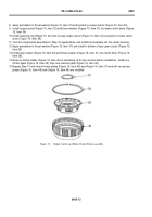
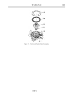
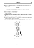
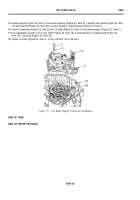
18.Install two new preformed packings (Figure 18, Item 26) and (Figure 18, Item 27) into face of brake cam
(Figure 18, Item 19).
CAUTION
Make sure you install seals so seal lips are in direction shown in Figure 18. If seals are not
installed correctly, components will not function correctly.
19.Install new seal (Figure 18, Item 23), seal lip down.
20.Install new seal (Figure 18, Item 22), seal lip up.
21.Apply petrolatum to packings (Figure 18, Item 26) and (Figure 18, Item 27) and seals (Figure 18, Item 22)
and (Figure 18, Item 23).
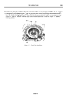
22.Hold two spring tension clips (Figure 18, Item 25) in position on brake cam (Figure 18, Item 19 ) as shown in
Figure 18.
23.Install bolt (Figure 18, Item 28) to keep clips (Figure 18, Item 29).
24.Torque bolt (Figure 18, Item 28) to 108 to 132 lb-in. (12 to 15 N·m).
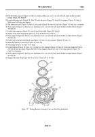
25.Assemble inner brake adjusting link (Figure 18, Item 24) and outer brake adjusting link (Figure 18, Item 25) so
you cannot see threads on inner link (Figure 18, Item 24).
26.Install slotted end of outer link (Figure 18, Item 25) into brake cam (Figure 18, Item 19) so that f at on link
(Figure 18, Item 25) is against free ends of spring tension clips (Figure 18, Item 29).
Back to Top

