TM-9-2520-272-40 - Page 387 of 620
TM 9-2520-272-40
0046
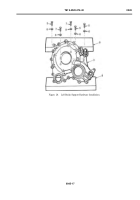
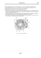
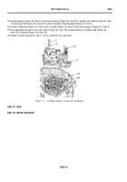
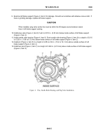
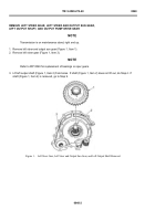
9. Examine left brake support (Figure 4, Item 2) for damage. Smooth out scratches with abrasive crocus cloth. If
there is grinding damage, replace left brake support.
CAUTION
When installed, plug valve scribe line must be within the 60-degree sector between raised
lines in left brake support casting.
10.Install plug valve (Figure 4, Item 8) f ush to 0.010 in. (0.25 mm) below inside surface of left brake support
(Figure 4, Item 2).
11. Install needle roller bearing (Figure 4, Item 9). Push needle roller bearing (Figure 4, Item 9) to a depth of 0.310
to 0.320 in. (7.88 to 8.12 mm) below inside surface of left brake support (Figure 4, Item 2).
12.Install pin (Figure 4, Item 8) to a height of 2.88 to 2.92 in. (73.2 to 74.1 mm) above outside surface of left
brake support (Figure 4, Item 2).
13.Install two pins (Figure 4, Item 7) to a height of 0.240 in. (6.10 mm) above inside surface of left brake support
(Figure 4, Item 2).
Back to Top

