TM-9-2520-272-40 - Page 486 of 620
TM 9-2520-272-40
0059
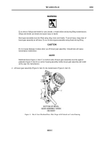
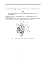
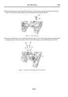
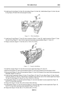
20.Remove bolt (Figure 6, Item 29) and washer (Figure 6, Item 30) that attach reverse signal tube (Figure 6, Item
27) to input and scavenge pump assembly (Figure 6, Item 31).
NOTE
If input and scavenge pump assembly must be sent to Depot Maintenance for overhaul, do
Step 21. If not, go to Step 22.
21.Install bolt (Figure 6, Item 29) and washer (Figure 6, Item 30) in input and scavenge pump assembly (Figure 6,
Item 31). Torque bolt (28) to 13 to 16 lb-ft (18 to 22 N·m).
22.Remove reverse signal tube (Figure 6, Item 27) from bevel gear assembly.
23.Remove clamp (Figure 6, Item 28) from reverse signal tube (Figure 6, Item 27).
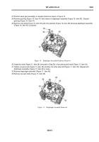
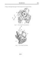
24.Remove connector (Figure 7, Item 32) and O-ring (Figure 7, Item 33) from input and scavenge pump assembly
(Figure 7, Item 31). Remove O-ring (Figure 7, Item 33) from connector (Figure 7, Item 32). Discard O-ring
(Figure 7, Item 33).
Back to Top

