TM-9-2520-272-40 - Page 494 of 620
TM 9-2520-272-40
0059
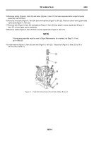
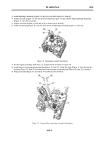
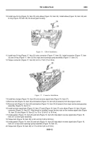
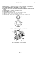
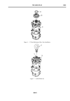
22.Install check valve (push-start) valve body (Figure 20, Item 22) onto bevel gear assembly. Install nine bolts
(Figure 20, Item 24) and nine washers (Figure 20, Item 23) that keep check valve (Figure 20, Item 22) in position.
23.Torque bolts (Figure 20, Item 24) to 17 to 20 lb-ft (23 to 27 N·m).
24.Install valve (Figure 20, Item 21), stem down, and spring (Figure 20, Item 20) into check valve (Figure 20,
Item 22).
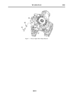
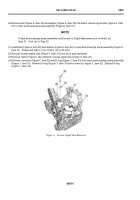
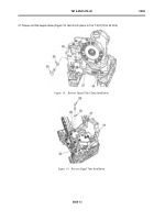
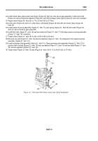
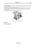
25.Install output oil pump assembly (Figure 21, Item 15) over spring (Figure 21, Item 20) and valve (Figure 20,
Item 21) and onto bevel gear assembly.
26.Install two bolts (Figure 21, Item 16) and two washers (Figure 21, Item 17) that keep output oil pump assembly
(Figure 21, Item 15) in position.
27.Torque bolts (Figure 21, Item 16) to 36 to 43 lb-ft (49 to 58 N·m).
28.Remove one bolt (Figure 21, Item 13) and one washer (Figure 21, Item 14) (if present) from output oil pump
assembly (Figure 21, Item 15).
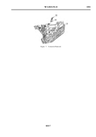
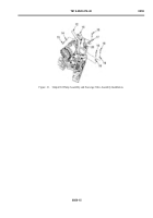
29.Install scavenge tube assembly (Figure 21, Item 12). Keep scavenge tube assembly (Figure 21, Item 12) in
position with one bolt (Figure 21, Item 13) and one washer (Figure 21, Item 14) and two bolts (Figure 21, Item
18) and two washers (Figure 21, Item 19).
30
.Torquebo
l
ts(F
igure21
,I
tem13)and(F
igure21
,I
tem18)to17to20lb-
f
t(23to27N·m)
.
Back to Top

