TM-9-2520-272-40 - Page 500 of 620
TM 9-2520-272-40
0060
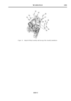
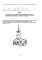
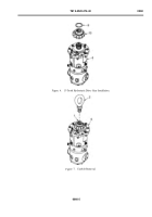
3. Install tool S-chain hook (Figure 2, Item 8) in eyebolt (Figure 2, Item 2).
4. Attach tool engine and transmission sling to S-chain hook and raise hydrostatic pump and motor assembly
(Figure 2, Item 6) out of transmission (Figure 2, Item 5) using hoist and trestle.
5. Lay hydrostatic pump and motor assembly (Figure 2, Item 6) on table and remove tool engine and transmission
sling (Figure 2, Item 6), S-chain hook (Figure 2, Item 8), and eyebolt (Figure 2, Item 2).
NOTE
Gears located on each end of the hydrostatic pump and motor assembly may be removed when
hydrostatic pump and motor assembly is in the transmission, or gears may be removed after
hydrostatic pump and motor assembly has been removed from transmission.
Hydrostatic drive gear (13-tooth) in Step 7 below is located on the end of the hydrostatic pump
and motor assembly where the eyebolt was attached.
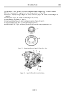
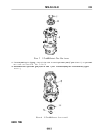
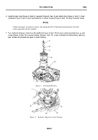
6. Using external retaining ring pliers, remove retaining ring (Figure 3, Item 9) that holds the 13-tooth hydrostatic
drive gear (Figure 3, Item 10) on the hydrostatic pump and motor assembly (Figure 3, Item 6).
7. Remove the 13-tooth hydrostatic drive gear (Figure 3, Item 10) from hydrostatic pump and motor assembly
(Figure 3, Item 6).
Back to Top

