TM-9-2520-272-40 - Page 502 of 620
TM 9-2520-272-40
0060
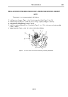
INSTALL HYDROSTATIC PUMP AND MOTOR ASSEMBLY
NOTE
Transmission installed on maintenance stand with input housing and right end cover assemblies
removed, and right end of transmission turned up.
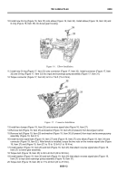
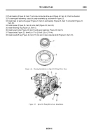
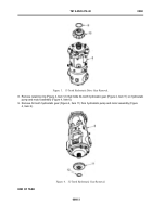
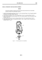
1. Install 32-tooth hydrostatic gear (Figure 5, Item 11) on end of hydrostat (Figure 5, Item 6) opposite hydrostat
mounting end, with larger shoulder of gear out.
2. Install retaining ring (Figure 5, Item 12) to hold gear (Figure 5, Item 11) on hydrostat (Figure 5, Item 6).
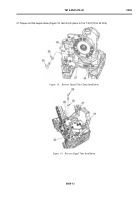
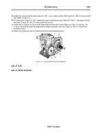
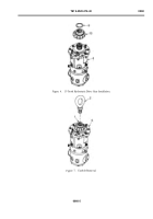
3. Install 13-tooth hydrostatic drive gear (Figure 6, Item 10) on hydrostat (Figure 6, Item 6) mounting end, with
shoulder of gear out.
4. Install retaining ring (Figure 6, Item 9) to hold gear (Figure 6, Item 10) on hydrostat (Figure 6, Item 6).
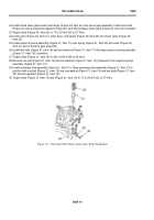
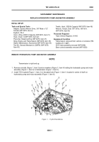
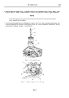
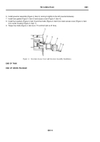
5. Install eyebolt (Figure 7, Item 2) in threaded hole (Figure 7, Item 1) located in shaft on mounting end of
hydrostat (Figure 7, Item 6).
Back to Top

