TM-9-2520-272-40 - Page 496 of 620
TM 9-2520-272-40
0059
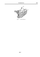
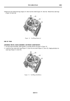
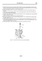
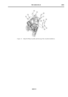
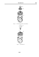
31.Push bearing (Figure 22, Item 7) onto input oil pump drive gear (Figure 22, Item 2). Push to shoulder.
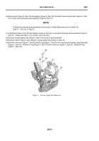
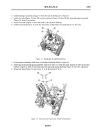
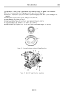
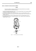
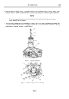
32.Put bevel gear assembly, output oil pump assembly up, as shown in Figure 23.
33.Install input oil pump drive gear (Figure 23, Item 2) and bearing (Figure 23, Item 7) onto shaft (Figure 23,
Item 43).
34.Install spacer (Figure 23, Item 6) onto shaft (Figure 23, Item 43).
35.Install retaining ring (Figure 23, Item 5).
36.Install seven bolts (Figure 23, Item 8) and seven washers (Figure 23, Item 9).
37.Torque bolts (Figure 23, Item 8) to 17 to 20 lb-ft (23 to 27 N·m).
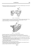
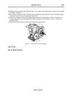
38.Install woodruff key (Figure 23, Item 11) into slot in input oil pump shaft (Figure 23, Item 10).
Back to Top

