TM-9-2520-272-40 - Page 499 of 620
TM 9-2520-272-40
0060
SUSTAINMENT MAINTENANCE
REPLACE HYDROSTATIC PUMP AND MOTOR ASSEMBLY
INITIAL SETUP:
Tools and Special Tools
Adapter, Socket Wrench Drive, 3/8” Male x 1/2”
Female (WP 0079, Item 2)
Eyebolt, 7/8-9
Hoist, Lifting, 2000 lb Capacity (WP 0079, Item 21)
Hook, Chain, S (WP 0079, Item 22)
Pliers Set, Retaining Ring (WP 0079, Item 27)
Sling, Engine and Transmission (WP 0079, Item 35)
Stand, Maintenance, Automotive (WP 0079, Item 40)
Tool Kit, General Mechanic’s (GMTK) (WP 0079,
Item 45)
Trestle, Hoist, 2000 lb Capacity (WP 0079, Item 46)
Wrench, Torque, Dial, 3/8” Drive, 300 lb-in.
(WP 0079, Item 50)
Personnel Required
Track Vehicle Repairer, 91H10
Equipment Condition
Transmission removed from vehicle or container (TM
9-2350-277-13&P)
Oil f ll tube assembly removed (WP 0006)
Steer control assembly removed (WP 0050)
REMOVE HYDROSTATIC PUMP AND MOTOR ASSEMBLY
NOTE
Transmission is right end up.
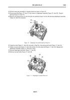
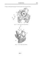
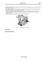
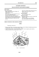
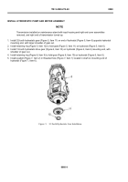
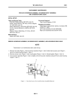
1. Remove six bolts (Figure 1, Item 3) and six washers (Figure 1, Item 4) holding the hydrostatic pump and motor
assembly (Figure 1, Item 6) to transmission (Figure 1, Item 5).
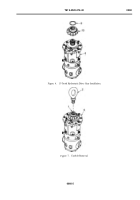
2. Install 7/8-9 eyebolt (Figure 1, Item 2) in threaded hole (Figure 1, Item 1) located in center of shaft on
hydrostatic pump and motor assembly (Figure 1, Item 6).
Back to Top

