TM-9-2520-272-40 - Page 478 of 620
TM 9-2520-272-40
0058
INSTALL BEVEL GEAR ASSEMBLY
NOTE
The center housing assembly may have been removed from the maintenance stand adapter or
may still be attached to the maintenance stand adapter depending upon previous maintenance
actions. If center housing assembly has been removed from the maintenance stand adapter,
refer to WP 0068 to install the transmission on the maintenance stand adapter.
Transmission center housing assembly is on maintenance stand, with input side turned up.
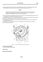
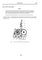
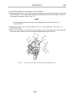
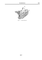
1. Attach three 7/16-14 x 1-1/4 bolts (Figure 3, Item 1) and three 7/16 inch washers (Figure 3, Item 2) through
lugs (Figure 3, Item 6) of multiple-leg sling and into three bolt holes (Figure 3, Item 3) in bevel gear assembly
(Figure 3, Item 5).
Back to Top

